


Sinclair C5 with Pedelec Mode
Implementing a Pedelec mode on a Sinclair C5 can be a complex task, so I decided to make use of the C5duino V2.0 board, which already measures the speed of the C5 and already has a space connector for another reed switch.
To begin with we need to remove the pedals and crank to give access to the C5 chassis.
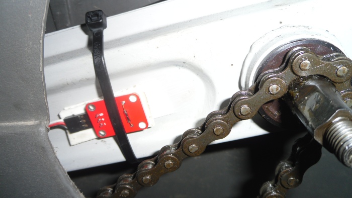
The reed switch I use to measure the rotations of the pedal crank, is heat shrink wrapped and placed on the Chassis using some double-sided sticky pads and a cable tie for good measure.

With the reed switch in position a cable containing +5V, GND and Signal needs to be attached to the reed switch and fed down the plastic conduit tubing under the the C5. The cable needs to end up at the C5duino control box at the rear of the C5.
The other end of the cable then needs to be attached to the connector marked RD2 on the C5duino circuit board.
The Software
With the switch in position we turn our attention to the software. The rules for the pedelec mode are simple: The motor can only be operated if it is being pedalled. In the future we can tie the vehicle speed with this calculation to ensure the motor is only used within a specified speed range.
To indcate to the C5 driver that the pedals are turning, and thus the motor can be used, we have a new icon at the top of the display (left) and if you're not pedalling the icon flashed Red (right):


On the Road
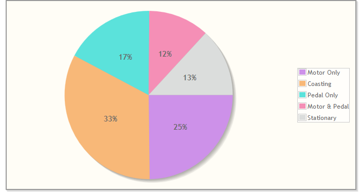
To give it a test and to also use the new data to construct some interesting charts, I took the C5 for a 2 hour 30 minute test drive.
Smart Drive Mode
In this mode the C5's top powered speed is limited to 15mph on the flat and less if going downhill, this will vary based on the gradient. There is no limit when on an incline.
The idea of the mode is to automatically coast as much as possible at the top powered speed. Frequently when I'm on the flat I keep the motor on all the time, even when it would be better to use the motor in short bursts. Smart Drive mode aims to use the motor in this way without the driver needing to constantly be pressing and releasing the handlebar switch.
For this mode to work correctly you will need to install an accelerometer and connect the X-axis analog output to A6 of the Arduino Nano in the control box. The accelerometer is attached firmly to the chassis and provides a means to determine if the C5 is going up/down a hill/incline.
