


Building the LCD Touchscreen for your Sinclair C5
Firstly you will need an Arduino mega + LCD shield + Touchscreen LCD module from Sainsmart (Sainsmart link). All links I provide are so you can locate the item I'm referring to quickly, you can then search and find the cheapest one yourself.
Once you have an Arduino mega you need to decide which I/O pins to use for the various sensors that we will be using. These are the pins I have used on the unit I have constructed:
- Motor Temp - A3 Input (Analog 3)
- Amp Reader - A7 Input
- Motor Relay - D17 PWM Output (Digital 17)
- Fan Control - D8 PWM Output
- Underneath Lights - D13 PWM Output
- Main Lights - D12 PWM Output
- Left Indicator Light - D11 PWM Output
- Right Indicator Light - D10 PWM Output
- Left Indicator Switch - D15 Input
- Right Indicator Switch - D16 Input
- Reed Switch - D18 Input (Interrupt enabled pin)
- Handlebar Switch - D19 Input (Interrupt enabled pin)
As you can see I have used most of the remaining available Digital Pins on the board (The touchscreen uses most of them!). It's important to use PWM enabled pins for the cooling fan. This allows you to vary the speed of the fan rather than simply having it simply on or off.
Interrupt Enabled Pin
With the touchscreen using most of the arduino pins you are left with only 2 pins that can be used to generate interrupts when their state changes (D18 and D19). Interrupt pins are important for capturing the state of the Reed switch that measures the speed of the C5. I have the reed switch attached to the right side of the box at the back, close to the right wheel. I also have a strong magnet attached to the wheel. As the wheel spins and the magnet passes the reed switch it generates a LOW signal which goes back to the Arduino and we can use to measure the speed.
You could use a loop in your code to read the state of the reed switch in each iteration, however this is very inefficient and with all the other code I have added to the main loop, the state change of the reed switch may be missed the faster the C5 is travelling. This is where interrupts come in. You specify a function to call in your Arduino code that is to be called when the pin state changes (from HIGH to LOW, in this instance on D18 for the reed switch) and run the relevant code for calculating speed in there. Interrupts are the equivalent to event driven programming in javascript and other modern languages.
If you use the same pin assignments as above you will not need to make any code modifications. You can of course change the pin assignments, the code changes will be very minor if you do.
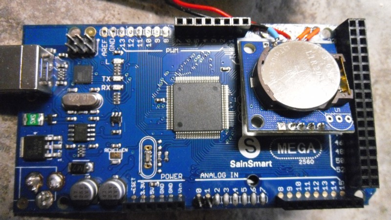
RTC Module
This is an important module which I have mounted between the Arduino mega board and the LCD shield. As well as providing a means to read the current date/time it provides 50 bytes of RAM that I use to store the total mileage the C5 has done plus the security PIN. As the RTC module (Ebay link) has it's own watch battery this information is not lost when you turn off your C5.
To connect the RTC module to the Arduino you need to connect the +5V and GND pins to the equivalent pins on the Arduino and then connect the SDA and SCL pins to the same 2 pins on the Arduino. It's important to note, the distance of any cable used to attach the RTC module to the Arduino isn't too long. I have in the past connected the RTC to the Arduino using a cable that was too long and found reading the RTC to be unreliable. That is why I have mounted my RTC directly next to the SDA and SCL pins on the Arduino.
When mounting the RTC above the Arduino and below the shield I found I needed to remove the Arduino Red reset button and the 6 ICSP header pins (we won't be using them anyway). You can of course leave them in and mount the RTC somewhere else but in order to fit the unit into the project box I needed to cram everything into as small a space as possible.
Measuring the Voltage and Ambient Temperature
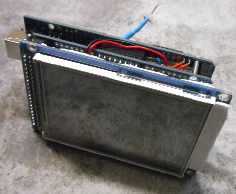
I created a small circuit board which contained a voltage divider to measure the external power supply voltage coming from the C5 battery and also added an LM35 temperature sensor which I connected directly to analog pin A0. The circuit board was then mounted above the LCD shield and below the actual LCD screen, soldered directly to the +5V and GND pins.
Again I needed to make use of all the available space between the shield and LCD circuit boards so I could fit the whole thing into the project box at the end.
Keeping it Compact
One of the goals of the front end LCD display is small size. After all we don't want the display to get in the way of operating the C5 and whilst pedalling it, I didn't want to hit my knees on it. The box I managed to fit it into was 130x68x44mm in size. It is a very tight fit at that size. I even had to file off about 2mm from the top and bottom of the LCD part of the circuit board to enable it to fit (vertically) in the box!
You could probably get away with using a slightly larger box which would allow you to have the voltage/ambient temperature circuit board and RTC board outside of the Arduino board and not have to modify the Arduino/shield boards as much.
Exposing the Arduino to the Back End Control Box
With the RTC module and the voltage/ambient temperature measurement in place, we now need to expose the necessary Arduino pins to the control box we will be building at the rear of the C5.
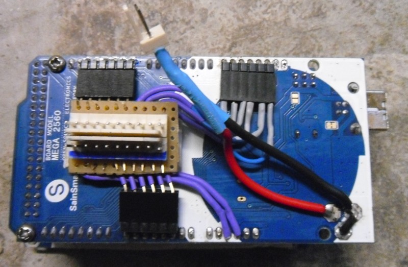
On my unit I have used two 10-way header pin connectors (Ebay link) that I have added under the main Arduino board which is connected to the necessary pins using angled header pins. This gives me the option of having access to 18 Arduino pins at the rear of the C5 (+5V and GND are the other 2 pins).
Initially I did not know how many pins I would be using so implemented a 1.5M long cable consisting of 20 wires. If you are implementing all the features of my unit you will need 1 wire for each pin I listed at the top of the page (13 pins) plus 2 pins for +5V and GND.
The connecting cable needs to be as long as the original cable that connected the POD to the control box. If you still have the original cable in place which contains 9 wires you can simply add an extra cable with 6 wires to make up the difference.
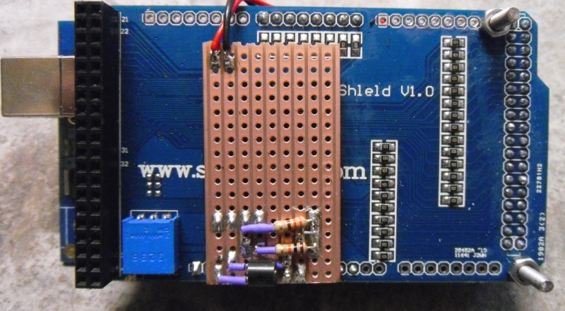
Analog Signals and Long Cables
One lesson I have learned whilst doing this is the importance of using some sort of shield to protect analog signals that need to travel down a long cable from external noise. There are 2 analog signals we need to transport from the back end control box to the display at the front: Motor Temperature and Motor Amp consmption. For these 2 cables rather than buy a cable with a shield already built-in I used regular kitchen foil to wrap the cable up in and then some heat shrink tubing to hold it in place.
Without the shielding around these 2 cables I found the readings from the temperature sensor tended to vary quite wildly (Especially when the motor was in use). The software does try to smooth out all analog readings by taking multiple readings over a short period and using the average, but we should also try to prevent unnecessary noise from distorting the analog signals.
Back-end Control Box
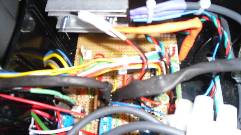
With the Arduino and it's LCD screen completed and located at the front of the C5 and a suitable cable linking the front LCD section with the back-end of your C5, it's time to build the circuit board that will turn on/off the motor, cooling fan and the lights. This, for me, was the most time consuming part of the hardware side of this project.
MOSFET? What's a MOSFET?
These little dudes allow the Arduino to use 5V signals to directly control 12V devices such as motors and lights. Firstly you will need to familiarise yourself with using N-Channel MOSFET transistors (MOSFET and Arduino Tutorial). This circuit is used 4 times (using IRFZ44N MOSFET) in my control box to control the following:
- Front/Back Light
- Left Indicator
- Right Indicator
- Cooling Fan
You can of course use other transistors such as the Darlington TIP120 rather than the MOSFET's for controlling the lights and the cooling fan. The one thing I would recommend doing is replacing the front/rear lights and indicator bulbs (if you are using indicators) with low power LED bulbs to keep the power consumption down. Since we will be implementing the indicator flasher in software you can use LED bulbs which I doubt work with a lot of flasher units, especially the original one supplied with the C5 indicators.
Detecting Button Clicks
The 3-way indicator button on the right side of the C5 under the seat, represents 2 switches and we also have the switch on the handlebar that, for now, is used to flash the front light.
This tutorial shows how to build a circuit that can detect a button press using an Arduino.
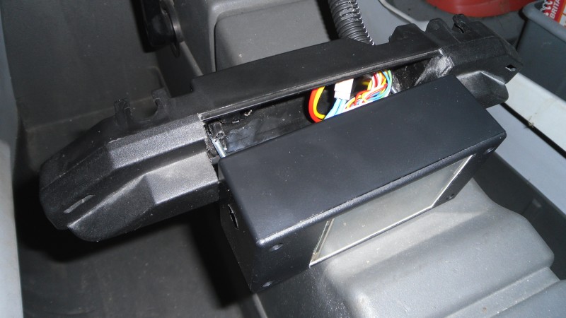
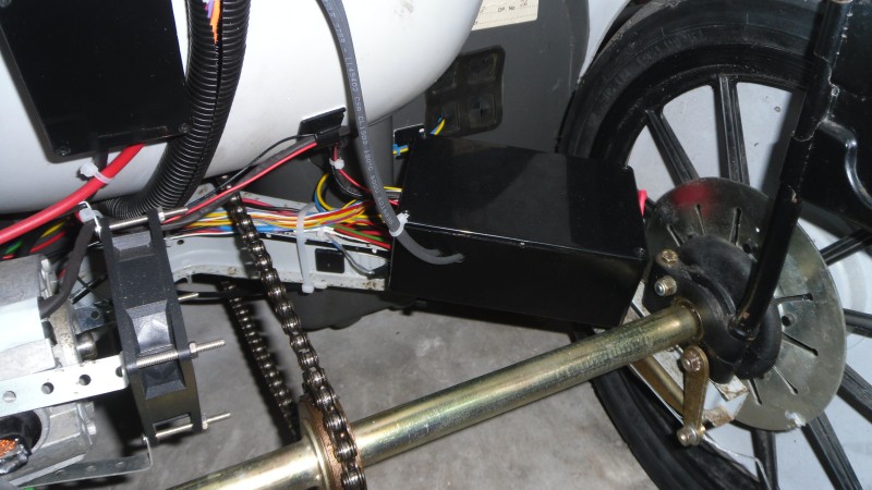
Once you have a circuit board with the above circuits soldered and ready to go it will need to be mounted inside a project box and anchored to the C5 frame at the rear. I have used a box measuring 150x100x60mm which is probably the largest size you can have in the space available. You may be able to construct a smaller circuit board and thus use a smaller box, but I figured it's out of sight at the back so size isn't as important as the from display box.

Measuring Speed
I have positioned my box close to the right wheel and is held in place with 2 cable ties. The reason I have it close to the right wheel is so I can attach the reed switch (Ebay link) to the side of it to measure the speed. You could of course attach the reed switch to something else, such as the main C5 frame. I attached it to the side of the project box simply because it was easiest and I didn't want to drill holes in my frame to attach it.
On the actual wheel, on the metal plate, I have a small magnet that is lined up with the reed switch. As the wheel spins, the magnet passes the reed switch and the magnetic pull on the switch causes it to briefly go into a LOW state which our software will use to calculate the speed. This is exactly the same method that most bicycle computers use to calculate speed.
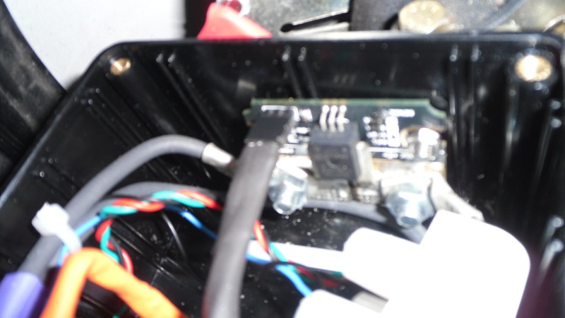
Measuring Motor Current
This module (Ebay link) is used to measure the current flowing through the motor and I have mounted it inside the control box (right-side) at the back of the C5. Connecting it up is fairly simple, all it needs is +5V, GND and a wire connecting it to analog pin A7 on the Arduino.
Software Download
Here is the Arduino software source code plus the libraries needed. The project will compile and run with just the Arduino MEGA/Shield/LCD/RTC connected, you are then free to implement whichever sensors you like. Without the RTC module in place you will not be able to get past the PIN entry screen unless to change the code to not attempt to read from RTC RAM, or just disable the PIN screen altogether.
Arduino 1.0.1 Project Source
Sainsmart LCD/RTC/PWM libraries
I've included the relevant Arduino libraries needed to compile the project as some of them (especially the Sainsmart LCD ones) are hard to find. Please note, the code is provided "AS IS," without express or implied warranty of any kind.
C5 Touchscreen Gallery
Here are some pictures of the unit that may help with the construction of your own.
