Please note: The forum is now closed to new submissions. All the existing forum topics and posts are still available, however new topics cannot be created. If you need Sinclair C5 advice please use the C5 Owners Facebook Group.

Karl posted:

](*,) ](*,) ](*,) ](*,) ](*,) ](*,) ](*,) ](*,) ](*,) ](*,) ](*,) ](*,) ](*,) ](*,) ](*,) ](*,) ](*,) ](*,) ](*,) ](*,) ](*,) ](*,) ](*,) ](*,) ](*,) ](*,)
They're coming to take me away ha ha, they're coming to take me away he he, to the happy farm were all is free.
For those of you who have never hear this, have a listen.
https://www.youtube.com/watch?v=hnzHtm1jhL4
or if you're like me.
https://www.youtube.com/watch?v=v9VMlLgc4vw

So now that I have the necessary data to find a replacement thermistor I've spent almost two days browsing the IN. Boy am I having fun.

I'll try and keep this as long as possible, oh! sorry short as possible.

Using the data that I've obtained I payed RS a visit and found a list of six possible thermistors. I tried to check the data sheets for the parameters pertaining to one of them and found four columns of data, 1006, 1008, 1009, and 1010, but no mention of which column was the correct one. So onto the phone to RS to find out which was the correct data sheet, after much who and ha and pumping data into the computer, plus a five minute wait to check with the tech dept, "sorry we can't help you". 15 minute call.

So into the IN and downloaded all the data covering these Thermistors, and this is what I found:

For any Part No. there a four variations, taking B57540G1103 as an example.
7003 B57540G1103+005 Dumet wires
7003 B57540G1103+007 Nickle-plated wires
8307 B57540G1103+000 Dumet wires
8307 B57540G1103+002 Nickle-plated wires

7003, and 8307 are the data sheets for the two beta variants. Eh! what ever happened to 1006 etc.?

TDK (Epos) inform me RS has missed out the suffix from the Mfr. Part No.

After cross checking the data from TDK & Epos's data and RS's I couldn't find any correlation between the five charts.

Back to RS, "can you supply me with the suffix numbers for these items?". Reply after five minute wait "sorry we haven't got any suffixes". "Why are your data sheets incorrect?", five miutes latter, "these are the data sheets provided by Epos, why don't you call TDK for help". "There's no point in calling TDK, they are not allowed to inform me as to what items are provided to a retailer or know why you have the wrong data sheets". "Once again sorry, I can only suggest you talk to TDK". My reply "Or better still, I go to another retailer, thank you I'll now go back to batting my head against the brick wall". 25 minute call. ](*,) ](*,)

Sorry, but I must go now, there's two men in clean white coats hammering on my door.
posted on: 13/02/2015 17:53:24

Area51 posted:

You could try rush industrial supply's they keep
A range of thermistors
posted on: 13/02/2015 18:42:46

Karl posted:

Hi 51,

thanks for the info, will check it out.

What in intensely annoying is some of the RS thermistors are good enough IF they match the 8307 criteria, but because RS doesn't know whether their item matches the 7003 or 8307 parameters there's no point in ordering from them.

There is also Farnell, but I did notice on the one and only thermistor from the RS list I checked with them, their price was considerately more expensive than RS. I had problems with Farnell's web page because I couldn't find a way to call up all the thermistors instead of their 'suck it and see' system. I wasted so much time I just gave up.
posted on: 13/02/2015 19:03:00

Area51 posted:

I know what you mean Karl I do order various
Parts from RS and Farnell and unless you know
What you want they are clueless
Andre from rush is very knowledgeable
I would think he can help


posted on: 13/02/2015 21:06:13

Karl posted:

Hi 51,

I had a look at their web site, but it appears that they only have four thermistors in their list, and no tech data is available.

And don't worry about me being carted off, those two men in their clean white coats were only there to clean the toilet.
posted on: 13/02/2015 22:36:12

Pep posted:

I too have called RS technical helpdesk and asked for details on specific items, only to have the details on the website read out to me !! and when they pass the info on to someone who will call back with the information, the call back has been useless, I don't know why they have a technical helpdesk

Sometime ago I carried out some simple tests with a C5 thermistor, if it is of any help these are the results I got

20 deg 8.2k ohm
45 deg 3.5k ohm
70 deg 1.7k ohm

pep
posted on: 14/02/2015 11:13:07

Karl posted:

Hi Pep,

many thanks for your input. Here's the data I've managed to collect.

Thanks to Chas and Perran, I have received the following data.

From Perran:
My conclusions are as follows:

The thermistor has a nominal resistance of 10K ohms at 25C. The Beta value of the original thermistor was ~ 3500.
This defined the slope of resistance change versus temperature. The two resistance values of 1100 and 900 ohms therefore correspond to actual thermistor temperatures of ~ 93C and 101C.

The closest I can find in a readily available thermistor of the right size is from Farnell part no: 970-7271. It has a slightly different Beta value and will sound warnings at 87C and 93C.

I found data from Polymotor which indicated that a max temp of 150C would be OK so there are some big safety margins here.

So now I can correlate the temperature to required resistance. So I checked the data for the recommended replacement and came up with the following data. As you can see from the data sheet below 1100Ω corresponds to ~ 84°C and 900Ω ~ 90.5°C as apposed to the original values of ~ 93°C and 101°C. For those of you who live in a hilly area this will be quite a negative effect. Seeing that the motor is good up to 150°C. I would not select this thermistor.

The selection of thermistors is limited mainly by the physical size, to all intents and purposes the beta factor is not so critical. As I mentioned before I found a few at RS that can be used but due to the missing suffix code it's not possible to select one. I've pumped the Mfr. Part No. into the IN, but up till now the only suppliers I can find insist on an minimal order of 1000 pieces.[woot][woot] I haven't finished the search yet, so with a bit of luck I'll come up with one.

There is a way to trick the circuit to obtain a better performance of the cutoff point, e.g. 120°C or so, this is still well within the safety margin. But I'll cover this subject at a later date when I find a suitable thermistor.


posted on: 14/02/2015 14:41:56

Area51 posted:

As the thermistor has to rely on electronics
To trip the circuit which can fail in my opinion
The best way to protect the motor is through
Cooling ie fit a cooling fan then as back up
You have the bimetallic trip then as back up
To that you have the thermistor
I fit thermistors to motor windings on a daily
Basis but they still burn out as you have to
Rely on the thermot unit or inverter tripping
The circuit
For me I use a cooling fan as this has more
Chance saving the motor
The bimetallic and thermistor would be
Back up to the cooling fan but I doubt
They would ever be needed
Cooling is the most important thing to any
Motor


posted on: 14/02/2015 17:26:13

Karl posted:

Hi 51,

I said to trick the circuit, not trip. That is, to up the warning and cutout points. This allows the C5 to operate longer on hills etc. I have always recommended a ventilator, but the thermistor is more important. The core of the armature is not cooled, this is the reason for fitting the thermistor were it is. It's possible to introduce a thermistor burn out warning circuit, but I think this is going overboard.

Forced air cooling will cool the surface of the armature as well the casing, but not the core. This allows a build up of heat in the armature but not so much in the casing. This means the thermal cutout activates a lot later than it would without forced air cooling. The temperature relationship between the armature and the case is greater with cooling than without. Therefore it is important to measure the core temperature.

The best solution is the belt and braces principle. Enlarged exit ventilation holes, a shrouded ventilator with temperature control, thermistor, and thermal cutout. At least that's the conversion I'm installing at the moment.
posted on: 14/02/2015 22:51:20

rusala posted:

Hi. Maybe this is a stupid question but what is exactly that you need? ;-) I do not know how the circuit works so I'm not sure if there is only some kind of threshold for example on 150*C or so? Maybe it would be possible to use a different element that a simple thermistor...
posted on: 17/02/2015 22:48:56

Karl posted:

Hi rusala,

A thermistor is the same as a resistor, but it resistance reacts to heat. The resistance of the type used in the C5 drops as temperature increases.

The thermistor is mounted in the core of the armature to measure the internal heat of the motor. It is connected to the ULA chip (the brain), and when the resistance of the thermistor drops to 1100Ω (~ 93°C)the ULA activates the aural warning signal, when the resistance drops to 900Ω (101°C)the ULA cuts the signal to the relay and the motor shuts down.

The original thermistor type is no longer available, so I am looking for a replacement that closely matches the original values. Problem is that there are many types of thermistors, as with resistors, but unlike resistors the thermal characteristics vary from type to type. The replacement recommended by Perran, the designer of the electrical system, is such the the critical cutoff point is 8°C lower than the original. If you live in an hilly area you will notice the difference, because the motor cuts out much sooner. 8°C higher would be no problem, in fact preferable.

The next problem is that the retailers can't quote what the characteristics are for the products they are selling, or as in the case of Farnell they don't inform you what the have in stock, you must tell them what you want. It's like playing a one arm bandit, sorry you didn't win try again. I'm looking for a thermistor that gives 1100Ω between 93°C and 100°C, and at 900Ω between 101°C and 120/130°C.

Simply slapping an unknown thermistor into the circuit could result in you travel a couple of hundred metres and the motor cuts out, or the C5 will not start, and even worse you end up with a burned out motor.

Should be quite simple, but unfortunately it's not.
posted on: 18/02/2015 14:24:59

rusala posted:

Hi Karl.

I know exactly what is the thermistor ;-) My question might not be clear. I was more interested in the "functionality" that you want to achieve in this case by the means of thermistor. I understand it now. So one question would be do you know the "B" parameter of the original thermistor? And maybe it's nominal resistance at 25°C?
It might be helpful but as you've said there are many types out there. Yesterday evening I was looking at few datasheets and did some calculations (with some vendors it is really difficult to calculate the actual values). Have you checked mouser.com? They have plenty different thermistors in stock although by a quick search I could not find one that is close to those values posted by Pep.

However there are few different solutions that come into my mind. The simple one would be to add offset to a thermistor that has the same "steepness" (approximated) of characteristic between 93°C and 101°C. We don't care about the absolute resistance as long as the difference is close to 200Ω. When you find such thermistor the only thing you need to do is add a resistor in series that will increase final resistance to 900/1100 ohms. For example if your thermistor has a resistance equal to 600Ω in 93°C and 800Ω in 101°C then simply add a 300Ω resistor in series with that (or something close from E12 like 270Ω or 330Ω).

Same thing may be done with resistor in parallel however it's a bit less intuitive and harder to calculate. If there is enough space available you can even connect two thermistors with different characteristics - something my friend has done lately in his car in order to compensate the error in coolant temperature gauge.

Another solutions would require either modifications to the ULA circuit or adding a bit more components and there are many possibilities here such as different thermistor + window comparator + transistor working as variable resistance or some linear temperature sensor such as LM35 and some similar OP amp based circuit. The easiest way would be changing the threshold points in ULA to correlate with different type of thermistor.
posted on: 18/02/2015 14:56:47

Karl posted:

Hi rusala,

thanks for your replay. I'll go through point for point.

1) Without any animosity, I think you haven't read all the posts, as all the data I have and that that you require are listed.

2)The resistance at 25°C and the the "B" parameter are of assistance but not binding, just the 900Ω and 1100Ω.

3) I have found more than one unit that can be used, but as quoted in previous posts I receive no adequate info.

4) Thanks for the tip with mouser.com, I'll give it a try later.

5) Your quote, "The simple one would be to add offset to a thermistor". This fact is know to me, this is the trick I was referring to in post #7, but I saw no point in opening the subject until I could could quote "use type xyz thermistor and a ***Ω resistor to obtain ???°C. You must take into consideration that the majority of the members have no grounding in electronics. Oh! and excuse me for being too precise in my description. Sinclair also used this method, there was one report of someone finding a 220Ω in series with his thermistor (factory original).
It would be easy to use Pep's recommendation, but I'd like to up the motor cutoff point to 120°C, and his unit is only recommended for use up to 125°C. That's just a little bit too close for my liking.

6) Your quote, "If there is enough space available you can even connect two thermistors". With a bit of ingenuity you may be able to fit two units, but I think it's complicating the solution. Plus the tube may be long, but the orifice in the armature is not very deep.

7) I think it's a VERY good idea to stay clear of the ULA, OK if you can replace it, BUT there's no replacements. If you can come up with a replacement I am 100% sure you will be exalted to the realms of the gods. But don't let us run away with reality concerning the thermistor, just keep it as simple as possible so the average member can conduct his own repair

Cheers.

Karl.

P.S. The physical size must also be taken into consideration, I don't have a tube available at the moment, but IIRC about 2mm Ø.
posted on: 18/02/2015 16:59:31

rusala posted:

Hi. To be honest I did go through all the posts but did not get some parts of it until I actually understood how ULA behaves which you posted later. So sorry for asking things that might be already answered earlier[blush].

As for finding the right thermistor or one that can be "tricked" by either series or parallel resistor I think you just focused too much on the lack of datasheets - if they can't help you at RS then just forget them ;-) For me it would be easier to first look through available and 100% known thermistors and then think of a way to make them useful. But of course everybody has their own way of working the solution to a problem ;-)

I know that many guys on the forum may not be so keen on electronics but there's no problem there as few of us may first discuss the solution and then describe it in simple manner, right?

I have just checked the circuit around ULA and I must say that the way how it handles the thresholds is a bit of a mystery so I agree - it's better not to touch it ;-)

So just to be sure that we're on the same page. You would like to have thermistor based circuit (by that I mean either just thermistor, or thermistor+resistor in whatever configuration) that will give you 1100Ω at 120°C and the point when you'll get the warning is less important. Is that correct?

I will try to find something also in few polish stores. maybe they have something of use on tme.eu...

Edited later:
It is just an assumption but I guess pretty good one ;-) ULA's thermistor inputs look to me as two comparators both set to 2.5V threshold.
At this point I want to apologise for my lack of knowledge. As you know I'm new with C5 and just learning these stuff. So I assume ULA is not some customized analog/digital IC but rather an Uncommitted Logic Array (which makes sense as those were also used in ZX Spectrum).
So if those are in fact just logic gates then 2.5V looks just like an threshold point in half of the power supply. Either way 2,5V reference is easiest solution with 5V supply on either analog or digital circuit. But this is not the way I got this 2.5V ;-) Heh never went the easy way ;-)

When we take thermistor, R9 (100Ω) and R20 (1kΩ) as a plain voltage divider here is what we get:
@93°C:
Rt = 1100Ω
V @ VTL (ULA's pin5) = 5V*(R20/(Rt+R9+R20)) = 5V*(1kΩ/2.2kΩ) = 2.27V
V @ VTH (ULA's pin6) = 5V*((R9+R20)/(Rt+R9+R20)) = 5V*(1.1kΩ/2.2kΩ) = 2.5V
@101°C:
Rt = 900Ω
V @ VTL (ULA's pin5) = 5V*(R20/(Rt+R9+R20)) = 5V*(1kΩ/2kΩ) = 2.5V
V @ VTH (ULA's pin6) = 5V*((R9+R20)/(Rt+R9+R20)) = 5V*(1.1kΩ/2kΩ) = 2.75V

So where am I getting with this to? Well, modifications to either one or both resistors R9 and R20 gives an opportunity to use much different thermistor then the original. For example the difference in resistance at 93°C and 101°C may be not 200Ω but 100Ω or 300Ω or whatever is suitable.
However there is one very important thing to remember here. Just after a quick look at control box circuit I think that the thermistor inputs are also used for overcurrent protection, right? So after changes in R9 and/or R20 there may be a need to also change R13 in control box (also R3 and R8 need some attention).

Anyway, this is just a though I had ;-) maybe it's helpful, maybe not
posted on: 18/02/2015 17:26:11

Karl posted:

Hi rusala,

you almost got it right. You're on page 1, and I'm on page 2.

It's 900Ω @120-130°C ± Ωs, low tolerance, max op temp 200°C, and max Ø 2mm, seeing that the warning comes in at 1100Ω. The warning point is built into the ULA, and the only way to get round that is to cut the leads to the buzzer.[omg]But as you posted the warning point is not really important, but not too close to the cutoff point.

I've had a long look at the mouser.com list. The only one that looks like it may be suitable is the Honeywell 112 series, but once again no 'B' parameter datasheets, plus 20% tolerance is not on the board.

I've come to the conclusion that to same time I'll just buy a set from RS, they're cheap, and conduct a heat test to find out which data sheet is applicable.

Your statement "ULA is not some customized analog/digital IC but rather an [h]Uncommitted Logic Array[/h]" made me smile. Now I wonder why did Sinclair term it a ULA.

Your assumption concerning R9 & 20 are correct, but as said before, I'm trying to keep people away from the POD. I believe in the KISS principle (keep it simple, stupid).

Your statement "Just after a quick look at control box circuit I think that the thermistor inputs are also used for overcurrent protection, right?". No, this is done by IC2.

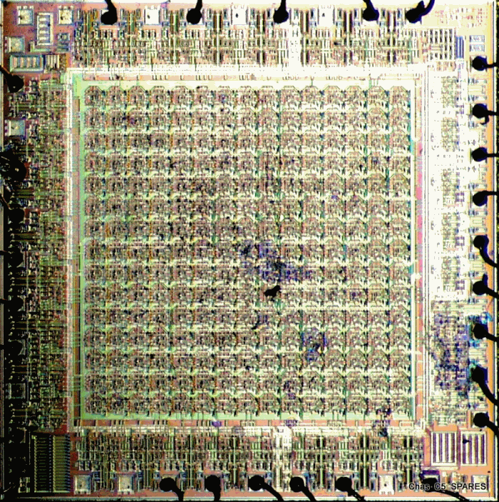
If you really want to delve into the ULA chip maybe Chas's photo may help.:-" :-"


Cheers.

Karl.

P.S. Send me your email address, I have some data that may help you.
posted on: 18/02/2015 19:39:19

rusala posted:

Did you consider using thermistor in SMD case for example 0603 or 0805?

Of course you are correct and IC2-2 is handling overcurrent protection but IC2-1 is controlling TR1 and TR2 which are affecting the same line as thermistor does. And because inverting input of IC2-2 and non-inverting input of IC2-1 are connected I assume they both contribute somehow to the overcurrent protection or at least IC2-1 is responsible for some kind of protective system. But now I also think that probably if somebody would like to play with R9 and R20 he doesn't have to do anything with R13. Well I'm 99% sure ;-)

I'll send you a PM with my mail address ;-)
posted on: 18/02/2015 20:03:02

Karl posted:

Hi rusala,

the 0603 or 0805 datasheets are in relation to glass bead thermistors, I don't know of an SMD that will fit the 2mm criteria. I think a 2mm unit would be too large as the shrink sleeveng must also be included.

Can anyone supply me with the inside diameter of an open thermistor tube?

Of course you are correct and IC2-2 is handling overcurrent protection but IC2-1 is controlling TR1 and TR2 which are affecting the same line as thermistor does.
Correct, but why complicate things. If the thermistor has to be replaced it's no problem to include a series resistor prior to sealing in the shrink sleeving, all the owner needs to know is the type of thermistor and value of resistor to buy.

Someone like C5mike would be prepared to offer a ready made unit in exchange for the duff one, plus costs of course.

I've been spending too much time searching the IN, when one is tired then mistakes creep in. So I'll wait a couple of days and start from the beginning again.

You should receive the data within the next month or so, sorry did I write next month, I meant next year.

Av phun.

Karl.
posted on: 18/02/2015 21:29:54

rusala posted:

This complication is just in case you cannot find a suitable thermistor but I believe you will ;-)
posted on: 18/02/2015 22:44:37