Please note: The forum is now closed to new submissions. All the existing forum topics and posts are still available, however new topics cannot be created. If you need Sinclair C5 advice please use the C5 Owners Facebook Group.

Karl posted:

Hi all,

some of you may recognise me, as KarlG, from forums other. I'm an expat living in Ottobrunn about 11 klicks from the heart of Munich.

I own four C5s from tatty to brand new unused, plus one that was relegated to scrap for spare parts.

Hope to have a bit of fun with you all, but will have to remain on this side of the ditch. :-({|=

In the mean time, av phun.

Cheers. Karl
posted on: 03/11/2014 23:07:08

dave posted:

Hey mate welcome thanks for the steel front wheel can't get on the other forum was banned for some Reson
posted on: 03/11/2014 23:21:05

Karl posted:

Hi Dave,

glad to be able to help out, was better than throwing it away.
posted on: 03/11/2014 23:52:08

SINCLAIR C5 CHAS posted:

Hi Karl nice to see you back
Chas
posted on: 04/11/2014 08:29:28

Dan posted:

Hi Karl and Welcome to the forum
posted on: 05/11/2014 19:06:35

Karl posted:

Hi Dan,

quite some time has passed since I first contacted you, well at least I made it in the end. Still looking for a solution to the pedelec problem.[-o<
posted on: 06/11/2014 19:21:11

davidmpye posted:

Is the solution you are after something that just disables the motor unless the pedals are also going round?

I could implement something like this fairly easily...
posted on: 14/11/2014 13:18:11

Karl posted:

Hi, thanks for the offer, I'd be most happy to hear your proposal.

I have a primitive solution that only covers the 'no pedaling, no motor', but not the cutoff at 25 kmh. In Germany, if the cops are not satisfied that the bike meets the pedelec regulations, they can give me a ticket to report to the TÜV (MOT) for a test. With my solution they would very quickly detect the non-conformity.

It is very hard to meet the correct pedelec regs., they are basically:

1. No direct motor drive, IOW first pedal then motor.
2. Motor power decreases with increase in speed.
3. Motor cuts off at 25 kmh.

Mostly, if points 1 & 3 are met there should be no problem. At worst it would be a light fine, and no loss of the C5.

There's a lot more to it that the above. I have a copy of the regs., it's a very good sleeping draught.

If the regs. are not met, then the following can happen:

Being charged with using an unregistered vehicle.
Charged with having no vehicle insurance.
Charged for not wearing a helmet.

Plus with 90% probability the C5 will be impounded and not returned. Plus, the fines here are quite stiff.

There's still a chance I'll use cypax's ULA replacement, or use Dan's touch screen system. That is, once I can read through all the posts and glean the in's and out's of Dan's solution, and see if meets my requirements.
posted on: 14/11/2014 14:21:47

davidmpye posted:

Hi,

Dan's solution is ideal - but now he's not (AFAIK) offering the PCBs etc it will require a little reengineering to build. I could do that (and probably will do something similar).

But if what you are after is *just* the pedelec functionality (at least to begin with), there are some microcontroller modules (Arduino Pro Mini clones for anyone interested ;-) which are available on eBay for £1.80 or so, and could easily implement the functionality you need.

You need to do exactly what Dan did for his solution with magnet/reed switches, but you can hardcode your limitations as above, without needing a touchscreen (though one could be added later).

So, the solution requires:

Routing the relay coil signal from the button via the microcontroller (several additional components to enable microcontroller to control the relay coil - transistor and a diode - pence only)
Reed switch/magnet on rear axle for road speed signal
Reed switch/magnet on pedal crank for pedal speed signal

And a small amount of code to implement the functionality you've mentioned.

I am interested in doing this and potentially selling the solution at moderate cost (maybe £20-30 for all the bits) as well as publishing all the code/PCB diagrams etc for anyone who wants to build their own :-)

David
posted on: 14/11/2014 17:40:18

Karl posted:

Hi David,

thanks for the quick reply, much appreciated.

Basically,

1. Do away with the motor button.
2. Motor operates only after pedaling.
3. Motor cuts out at 25 kmh.
4. No radical changes to the C5 ccts, i.e. the OS remains in it's original state.
5. No programing involved.

Touch screen etc. can come at a later date. I just want to be able to get out onto the road without having to look over my shoulder all of the time. OK!, I could fit some mirrors to solve that problem.

My trade was in electronics, but at 73 I'm pushed for time and don't want to waste what's left in learning programing.

I was in contact with Phil (cypax), a couple of years ago, concerning his unit, as the software wasn't available. He seemed to be a bit on the cool side, so I dropped the idea.

If you have, or can construct, a unit that will fit the requirement listed above, and you are prepared to sell, count me in.

I have most of the gear required such as Reed switches, relays, etc.

Regards.

Karl.
posted on: 14/11/2014 18:52:49

davidmpye posted:

Hi,

Certainly most of this could be done - but I do foresee a problem with doing away with the motor button.

The problem is this:

If you stop pedalling, it will take a little while before the controller will know this. If it only gets a signal per revolution of the crank, and it is acceptable to pedal at maybe 1 revolution every 2 secs, it will take at least that time for it to know you've stopped pedalling, by which time you have hit a wall...

So I'm not sure it is safe to do away with the control button but certainly having the control button, but making it only work <=25kph and when pedalling is easily doable.

David
posted on: 16/11/2014 00:00:15

Karl posted:

Hi David,

quite right, but if three or four magnets, or even more, are mounted on the pedal chain wheel, this should reduce the problem.

I also have a few brake levers with built in micro switches, these could be integrated into the motor control cct. I would prefer not to use these levers if possible, I only have two sets, and four C5s to convert.

Best regards.

Karl.
posted on: 16/11/2014 01:52:42

Karl posted:

Hi David,

while on the subject of safety, there's on point I would like to bring up.

If there's a single reed switch fitted to the chassis it would be possible to turn the pedals to the activation point and stop pedaling, this would result in the motor being switch on for 100% of the time. This of course contravenes the pedelec regs. Or, if the C5 is pushed backwards the motor could be activated.

If two switches are fitted so that at no time the two can be operated simultaneously, see diagram below.

As the pedal turns RS1 closes for a short period partially charging the capacitor then reopens, the pedal rotates further and activates RS2 then deactivates. At no time are both switches in the closed position. After a couple of turns from the pedals, at the right rpm, the capacitor charge is high enough to active the motor cct.
posted on: 16/11/2014 15:47:09

davidmpye posted:

Hi,

See attached for a quick and dirty schematic that is how I'd do it (bearing in mind I'm far more of a digital electronics guy ;-)

The microcontroller board is <£2.

There are two reed switches - one providing a pulse every time the crank rotates, another providing a pulse when the rear axle rotates.

The output is the signal to the base of a transistor controlling the motor relay coil.

The microcontroller uses the rising (or falling) edges of the pulses - that avoids the scenario you mentioned of lining the crank up with the switch and not moving it. So a continous high (or low) signal won't trigger - it has to be the pulses.

So, in mine, the relay coil can only be enabled when 3 tests are met:

1 - pulses from the crank rotation (if you want 2 relays to be more sensitive to speed, then fine ;-)
2 - pulses from the axle rotation indicating speed <25kph
3 - the drive button enabled - this is done directly on to the supply to the transistor collector.

I still don't like the idea of the motor enabling without driver control myself - and it also avoids the problem you mention about a reversing C5 having the motor triggered. Also if somehow the microcontroller crashed etc (obviously my code is always 100% perfect 
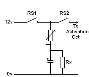
) then it still fails safe ;-)

I suppose you'd need 3 microswitches on the crank to work out which direction it was rotating in, which is why I don't like having to do it that way!

Still, it meets the definition of the pedelec rules (based on what you said! )

And can be done with a small component count and <£10!

David
posted on: 17/11/2014 03:45:03

davidmpye posted:

(Also, bear in mind it's 0340 here and I've got a 3 week old insomniac baby strapped to my chest ;-)

David
posted on: 17/11/2014 03:46:24

Karl posted:

Hi David,

(Also, bear in mind it's 0340 here and I've got a 3 week old insomniac baby strapped to my chest ;-)
I was wondering about that. I closed down at about 1:00 your time, without an insomniac baby. At first I thought you were also a night owl, like me.
posted on: 17/11/2014 14:02:59

Karl posted:

The reasons for wanting to eliminate the motor button are

1. Having a sore thumb at the end of a long journey.
2. On the left hand side of the handlebars will be a combi-unit with horn button, light switch, and turn indicator switch. On the Right is the switch for the electronic gear change.

With the analog system, Rx bleeds the capacitor charge. When the pedal wheel doesn't turn fast enough there isn't the required voltage to trigger the cct. But I must admit it doesn't eliminate the motor from working when one backpedals. Seeing that pushing a C5 backwards fast is a strict no go, then the problem of the motor cutting in is eliminated.

I must admit your solution is beginning to whet my appetite. Just one small point, the more magnets the merrier. With the loss of a single magnet you sit high and dry, with the loss of the third magnet things are not quite right, but you can still get home.

There is still the problem of the motor operating when you backpedal. It wouldn't worry me, but it might worry the cops.
posted on: 17/11/2014 15:01:35

Karl posted:

Sorry but I can't edit my last post.

IIRC there is provision for a micro switch on the right hand side of the handlebars (horn button?).

Can anyone confirm this?

Cheers.

Karl.
posted on: 17/11/2014 15:06:38

davidmpye posted:

There should be, yes.

Another idea would be to have a latching switch to avoid your sore finger, but still give you something to whack in an emergency to stop the motor cold :-)
posted on: 17/11/2014 18:32:43

Karl posted:

There's something just cropped up in my mind, this dammed pedelec system does not allow for coasting. I must have the power button.

I don't think a latching switch would be a good idea. Press the button and the latch operates, now how do you get it to 'unoperate'?

The idea is good, and stated the rusty cogs, in my head, turning. The solution would be a solid state flip-flop relay, press once on, press again off. Solid state has the advantage of eliminating the contact bounce.

While on the subject of solid state relays, it might be an advantage to replace the existing power relay with a solid state one.
posted on: 17/11/2014 23:31:12

davidmpye posted:

There's something just cropped up in my mind, this dammed pedelec system does not allow for coasting. I must have the power button.

I don't think a latching switch would be a good idea. Press the button and the latch operates, now how do you get it to 'unoperate'?


If it's a latching switch, just press it again, and it will unlatch?

The idea is good, and stated the rusty cogs, in my head, turning. The solution would be a solid state flip-flop relay, press once on, press again off. Solid state has the advantage of eliminating the contact bounce.

Well, the microcontroller could do that itself via another of its' inputs, but the point of having the button outside the microcontroller was a safety one in that it would allow you to cut the motor if the microcontroller went rogue/shorted/faulty. Perhaps excessive paranoia on my part....

While on the subject of solid state relays, it might be an advantage to replace the existing power relay with a solid state one.

Possibly ;-) Then again, you might as well end up with a PWM speed controller!

David
posted on: 17/11/2014 23:58:51

Karl posted:

I'll leave the power button up to you. As I said I'm open to any ideas, and as I have no idea concerning microprocessors, I appreciate any help I can get.

PWM at 12v is worthless, too much voltage loss though the controller. With 24v and a 12v motor the loss is not noticed, but the motor does not receive the full 24v.
posted on: 18/11/2014 00:42:16

Karl posted:

It appears that microprocessor terminology has altered from the original electronic terminology.

Even today a latching switch cct has two buttons, one to latch and a second to unlatch, often used to control electric motors.
http://www.dummies.com/Section/id-DUMMIES2_CONTENT_SEARCH_RESULT.html?query=what-is-a-latch-circuit

A flip-flop, or bistable switch cct uses one button, first press on, second press off.
http://www.dummies.com/how-to/content/digital-electronics-what-is-a-flipflop.html

Hence my confusion when you mentioned a latch switch.
posted on: 18/11/2014 15:11:41

davidmpye posted:

Hi!

I didn't so much mean a switch circuit, just a switch with a locking mechanism

e.g.
http://www.maplin.co.uk/p/green-locking-push-switch-n99aq but this is something you can tweak to your personal preference

If you're interested in giving this sort of thing a go, I will write the code for the controller. You'd need to do the mounting of the reed switches/magnets and the wiring, and a few of the other components eg suitable transistor, a diode for back EMF from relay coil etc, but with an electronics background I'm sure that's no issue!

What I'd suggest was that I'll send you the board and a programming interface for it, then I can give you code updates which you can then upload onto the board for testing. (without this, the board would end up racking up a lot of airmiles between UK and .DE!)

None of these electronic bits are expensive (certainly not to the extent microcontroller stuff used to be!)

The software is a free download (www.arduino.cc) and the interface is:
http://proto-pic.co.uk/ftdi-voltage-selectable-board/ (£10)

(A few cheaper ones might be on ebay - it just needs a mini USB lead to connect to a computer - mac/win/linux are all adequate!)

The board itself is an arduino pro mini clone (I have a pile of them for £2, having bought a batch from China!) Happy to supply one for that + postage! They are happy to run directly off 12V, and have their own small 5V regulator on board.

If you're not keen, that's also fine - I'm just interested to help if you are!

David

posted on: 19/11/2014 00:08:06

Karl posted:

Hi David,

as you quoted.
If you're not keen, that's also fine
You are quite right, I not keen, I'm just sat here on hot coals, and hounding the computer around the flat, beating the hell out of the poor thing because there's no emails.

At the price you quoted, what the hell if it don't work, but I hope to hell it does.

Please go ahead, just attach the lead to my collar, and I'll follow.:-"

Cheers.

Karl.

P,S, It looks like your post count has stuck at 6, it's been like that for some time now.
posted on: 19/11/2014 00:32:17

davidmpye posted:

Awesome :-)

Let's have a go and see what we can collaborate on then!

Probably easier to do some of the next bit by email otherwise this thread will never end - we can come back here and post how we did it later!

Drop me an email [email protected] and we'll get working!

David
posted on: 20/11/2014 07:09:05

Karl posted:

Just lead me down the path Phred, oops sorry, David.[blush]

I thought it might be a good idea to open the subject under 'Sinclair C5 Projects' so that other members from this side of the ditch can follow the progress.

Will make contact as you suggested, and we'll take it from there.

Cheers.

Karl.

P.S. See you're still stuck at 6 posts.
posted on: 20/11/2014 07:54:59