Please note: The forum is now closed to new submissions. All the existing forum topics and posts are still available, however new topics cannot be created. If you need Sinclair C5 advice please use the C5 Owners Facebook Group.

Dan posted:

Once again I am looking for willing BETA testers (Dave & Marra are 1st in line) for this C5duino Control Box project.

[center][/center]

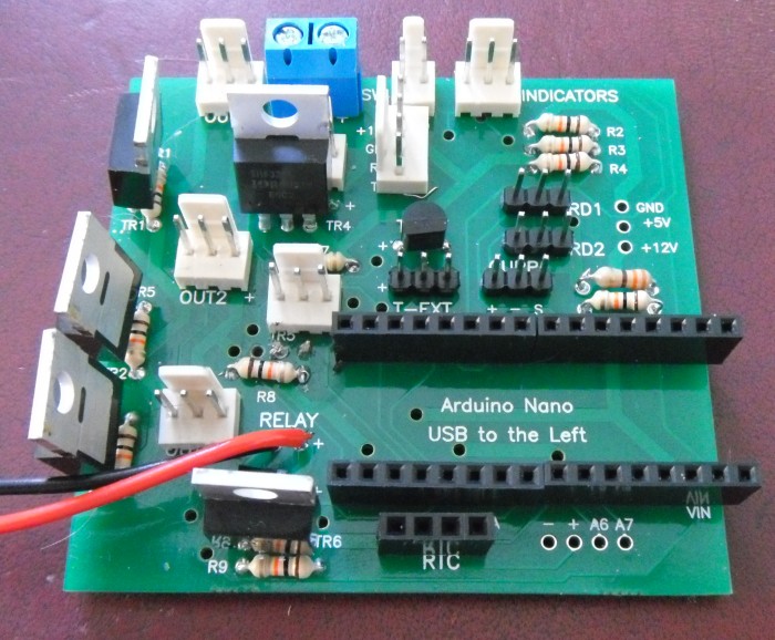
I would like to emphasize that only people who have a soldering iron and are able to solder should apply as there will be a lot of it. I will be providing the bare board only, I cannot afford to populate it with all the components too.

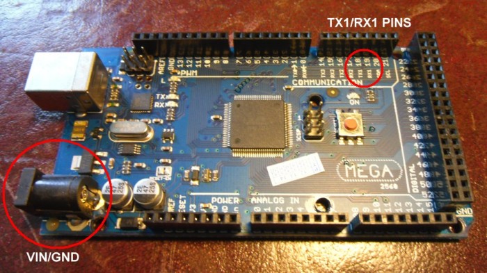
You must also be happy downloading the software, connecting the Arduino's to a Windows PC via USB and uploading the software to the boards. All software is free!

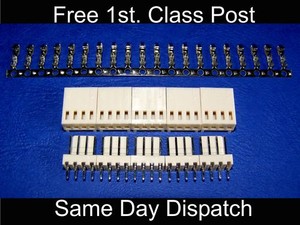
There are a lot of components you will be required to purchase (some of them expensive) and put together. Most will be from ebay or wherever you prefer. A full component list will follow.

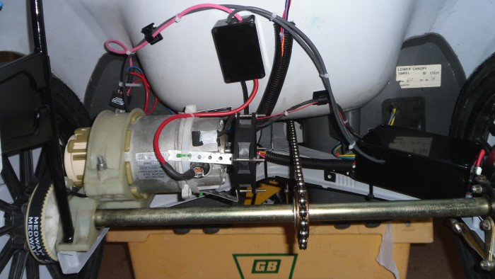
You will also need to add various connectors to your existing C5 wires such as handlebar switch, indicator switch, indicator lights, main lights etc as these all need to be connected to the circuit board.

By requesting to enroll in the BETA program you agree to the following:

1. You understand this is a module still in the testing process and that it may or may not function as specified.

2. Using this module in your C5 is entirely at your own risk. Whilst every effort has been made to ensure the module works as specified, C5owners.com will not be held responsible for your use of this module in your C5.

BETA SOFTWARE DISCLAIMER
THE BETA SOFTWARE LICENSED HEREUNDER, PRIMARY PURPOSE OF THIS BETA TESTING LICENSE IS TO OBTAIN FEEDBACK ON SOFTWARE PERFORMANCE AND THE IDENTIFICATION OF DEFECTS. THE LICENSEE IS ADVISED TO USE CAUTION AND NOT TO RELY IN ANY WAY ON THE CORRECT FUNCTIONING OR PERFORMANCE OF THE SOFTWARE AND/OR ACCOMPANYING MATERIALS.

If you agree to the above and want to participate then register your interest below.

Project documentation will follow in the coming days!

Thanks!

Dan
posted on: 20/05/2013 20:21:10

dave posted:

I said it would be ready for the end of the month and still a few days to go put me down mate
posted on: 20/05/2013 21:54:02

dave posted:

ordered the screen nano v3 and rtc module already
posted on: 20/05/2013 22:03:24

Dan posted:

I said it would be ready for the end of the month and still a few days to go put me down mate


Yeah I knocked out the soldering in a couple of hours on Monday, it's just the software now which needs attention as there's quite a few bugs in it
posted on: 22/05/2013 05:48:45

dave posted:

Looks like I'll be going to maplins very very soon.
posted on: 22/05/2013 08:35:28

Dan posted:

I'll get the board posted out to you tomorrow Dave. Do you know what you need to solder onto it?
posted on: 22/05/2013 17:59:26

dave posted:

just got in a lot of small little bits lol thought you was doing a full list of parts that are needed should get the screen Friday got it for 33 quid uk seller
posted on: 22/05/2013 21:45:18

dave posted:

No soldering I hope lol I never got a fee ula chip mod
posted on: 22/05/2013 21:53:18

Dan posted:

No soldering I hope lol I never got a fee ula chip mod


Nope you didn't want one, you wanted one of these. See here.


The above is what you'll be getting. This is what you need to add to it:


The component list is here. Have a good read through of that page, especially the pictures at the bottom that show the board before/after construction.

Soldering will be necessary, I'll hang on to the board until your 100% sure you can do it!
posted on: 23/05/2013 06:09:23

dave posted:

I can do it matey I go down the list hand get the bits
posted on: 23/05/2013 09:00:54

dave posted:

all parts ordered matey
posted on: 23/05/2013 09:52:54

dave posted:

screens arrived dan have you got a link to the header for the nano and rtc then i can get them ordered to cheers mate
posted on: 23/05/2013 12:04:04

Dan posted:

screens arrived dan have you got a link to the header for the nano and rtc then i can get them ordered to cheers mate


Hi Dave,

I posted your board to you today

As for headers, try these they're quite expensive, maybe you can find cheaper ones? You just need 2 strips of 15. I usually get 4 x 8pin ones as they're more common.

Are you going to implement the extra external lights? I have a set of Blue LED strip lights under the C5 that the middle button on the display controls.

If so, you'll need to double-up on the header pins for the Arduino as it gets in the way of the Mosfet (I didn't take into account the overhang of the Nano's USB socket when designing the PCB). If you're not going to use external lights, you don't need to put anything in TR5, R8 and OUT4.

For the RTC, try this one.

I'm impressed you've got most of the stuff, you'll have to keep a record of how much its cost you. Also, post some pics of you're progress in a new thread so I can see how you're getting on and spot any errors!

What I didn't explain on the project page was what lights etc go where:

BATT = Battery
SWI = Handlebar switch
INDICATORS = Guess?? Left switch/Common/Right switch
OUT1 = Left Indicator lights
OUT2 = Right Indicator lights
OUT3 = Front/Back Lights
FAN = Motor cooling fan (Optional)
OUT4 = External lights (Optional)
RELAY = Motor Relay
T-INT = Ambient temp (LM35)
T-EXT = Motor temp (LM35 strapped to the motor)
CURR = Current sensing module
RD1 = Main reed switch (Back wheel)
RD2 = Unused reed switch
RTC = Real Time Clock module

What size project box have you got to put it all in?
posted on: 23/05/2013 12:58:26

dave posted:

Hi dan the box is 145x100x60 the rtc is the same 1 but £1.77 from hong kong are the headers for the clock the same as the nano ? Up to now its £45.06 for the back and £33 for the screen
posted on: 23/05/2013 21:57:47

dave posted:

Dan on the comp link to ebay it comes up with header pins ?
posted on: 23/05/2013 23:05:16

dave posted:

Have you got a link to the blue strip lights ? The box is 150 not 145 and will get all parts for Wednesday ebay says
posted on: 23/05/2013 23:37:52

Doc Holliday posted:

Hi Dan,
I would like to test too!
What will I need?

greets
Ralf
posted on: 24/05/2013 05:13:03

Dan posted:

are the headers for the clock the same as the nano ?


Yes, a row of 4 need to be soldered to the board. The RTC should come with male headers already soldered on.

Dan on the comp link to ebay it comes up with header pins ?

Yep they're the headers you need.

Have you got a link to the blue strip lights ?

Not 100% sure, I got them ages ago. But any low power 12V LED strips will do, try this one. I have 2 of them, 1 under the front and 1 at the rear.

You could always add the strip lights later on, after everything else. TBH, where I've placed them, you only notice them on at night


posted on: 24/05/2013 06:12:52

Dan posted:

Hi Dan,
I would like to test too!
What will I need?


Hi Ralph,

The project is split into 2 sections, a new control box (C5duino) and the LCD screen. Please see:

C5duino Control Box
LCD Touchscreen

It will involve re-doing the electrics in your C5 completely. How you mount the display is up to you, I've used an old POD case and bolted a small project box into it which contains the screen:


Thanks!

Dan
posted on: 24/05/2013 06:17:33

Dan posted:

the box is 145x100x60


This is the box I have:


I've bolted the Relay onto the side of the box and the Current module is also bolted to the right side. The board just sits on the bottom, its not held in place, when all the wires are plugged into it can't move around.


To make it easy to apply software updates I leave the USB cable in the Nano and run it through the back with the indicator switch wires and store it under the seat.

posted on: 24/05/2013 06:44:19

dave posted:

whats the box on the back of the seat?
posted on: 24/05/2013 08:41:29

dave posted:

what can you use if you have not got a small pcb with pins on for the screen end ?
posted on: 24/05/2013 08:44:44

dave posted:

dan do you want the evtra bits that are left over ? dont think ill need them ?
posted on: 24/05/2013 11:59:37

Dan posted:

Hi there Dave,

whats the box on the back of the seat?


That's just a terminal block connecting the motor cables to the ones from the battery (+12V) & control box (GND) with a 1N5404 diode to stop back EMF damaging the relay[omg]. You'll need to add a diode to your setup too.

what can you use if you have not got a small pcb with pins on for the screen end ?

Do you have a 4-way connector?


You could just solder wires onto each pin at the bottom and solder them on to the Arduino pins. Have you got the cable that joins front to back? I used this alarm cable as its got a shield built in. You could solder the cable wires directly to the Arduino, though this makes it difficult if you want to remove the screen for any reason.

dan do you want the evtra bits that are left over ? dont think ill need them ?

You can do certainly Though I'd keep hold of everything until you're up and running!

Are you're indicators all original? I wouldn't want to be butchering the ends of a working indicator set, it'll devalue it 
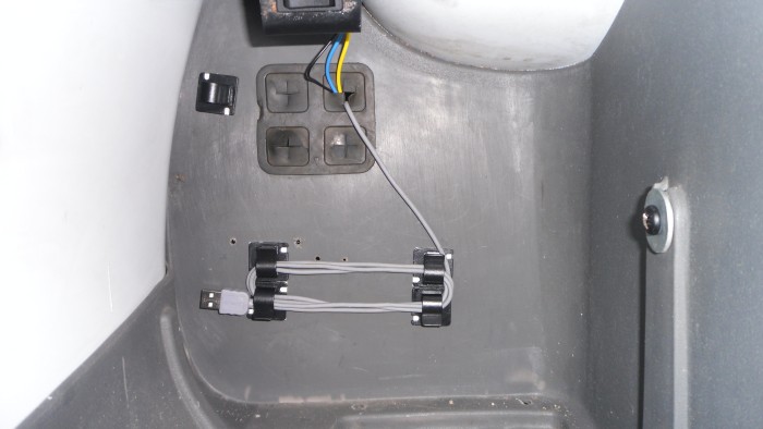
My indicators didn't have any of the original wiring so I didn't worry about messing with the wiring.

Thanks!

Dan
posted on: 24/05/2013 12:44:31

dave posted:

Got 4 clear lcd indicators to use going to put this kit on the black c5 that's got no wiring
posted on: 24/05/2013 21:52:43

dave posted:

I could solder the pins then cut the wires at the back of the box and put a male and female plug on ?
posted on: 24/05/2013 23:01:15

dave posted:

Board just got here nice work dan
posted on: 25/05/2013 10:10:49

Dan posted:

[quote=dave;301]I could solder the pins then cut the wires at the back of the box and put a male and female plug on ?[/quote]

Yep sounds like it could work, if I do develop this further I'm going to see if theres a way to just connect the front to the back through the usb socket on the arduinos, it'd save a load of hacking wires up


[quote=dave;301]Board just got here nice work dan[/quote]
Cool, you could start some of the soldering soon then??
posted on: 25/05/2013 12:17:47

Dan posted:

can you do me a favour and put a pic on were the wires r soldered to the board for the screen with the wires on plz

This is a picture from the top of the MEGA board if that's of any use.


And one from the back, you should be able to see whats going on. This is the arduino I used on my early prototype screen which is why there's lots of angled header pins on there. All you need is TX1, RX1 (top-left) and the power connector (VIN & GND bottom-right).

posted on: 25/05/2013 20:03:29

dave posted:

So u go for the bottom end then ?
posted on: 25/05/2013 20:17:51

Dan posted:

So u go for the bottom end then ?


Yeah, the shield board sits on top of the arduino so theres no easy access to the pin sockets on top of it. Its up to you, you may have a better way to do it
posted on: 25/05/2013 20:21:01

dave posted:

it would be better using usb ?
posted on: 26/05/2013 09:35:48

dave posted:

Dan have you got a link to a suitable handle bar switch or a trottle if you can use 1 ?
posted on: 26/05/2013 10:42:21

Dan posted:

it would be better using usb ?


Its on my wishlist, at the moment you need to use the TX/RX pins instead.

Dan have you got a link to a suitable handle bar switch or a trottle if you can use 1 ?

The board can only use a relay so you need a switch. I just re-used the normal C5 handlebar switch, has your C5 not got one???? Not sure of any suitable replacements, probably an ebay job

I just ordered a uni-8 board so I'll be joining the 24v club soon. It may be my turn to ask you for information Dave
posted on: 26/05/2013 11:21:19

dave posted:

24v good man you will never go back to 12 v a good kit to get uni 8 and no handle bar switch what's your next project 24v touch ?
posted on: 26/05/2013 12:06:03

dave posted:

So I can just solder the 4 core alarm cable to the 4 points on the board
posted on: 26/05/2013 12:30:39

Dan posted:

So I can just solder the 4 core alarm cable to the 4 points on the board


Erm, you can do. It just makes it harder later on if you need to remove the board later on. That's why I put the connectors on everything. Its entirely up to you, I suppose it also depends on how you lay out your project box.

what's your next project 24v touch ?

Yep, I want to get one running on 24V and then look at sticking a touchscreen on it.
posted on: 26/05/2013 14:15:31

dave posted:

Cheers was going to put a 4 pin plug outside of the box so I can take the screen off if needed can you do a.wiring diagram or is that another topic ?
posted on: 26/05/2013 15:14:57

Guest posted:

Would love to see a 24V version
posted on: 26/05/2013 19:46:13

dave posted:

I would like 1 to marra soldering stopped waiting for the postman to drop the headers off rtc and cur sensor and another mosfet only got 5 needed 6 got everything else on the shopping list
posted on: 27/05/2013 15:32:18

dave posted:

What now dan?
[albumimg]5[/albumimg]
posted on: 28/05/2013 17:21:35

Dan posted:

Nicely done Dave. You're not far off then.

I gave mine a test on Mon, with the C5 sat on a crate and had the motor on for ages and the Arduino nano got a bit too hot for my liking

So I'm thinking of strapping a heatsink to its regulator or maybe add a separate 12v regulator to the pcb somewhere to keep the voltage within the acceptable range for a Nano.
posted on: 28/05/2013 18:10:45

dave posted:

I've put a 4 pin plug on the wire so you don't need to take the screen out to if you take it apart just unplug job done and you can hide it it the trunking aswell
posted on: 28/05/2013 18:41:03

dave posted:

What can I get on with now ? Can you not just put a small fan in the control box ?
posted on: 28/05/2013 18:55:47

Dan posted:

What can I get on with now ?

Have you got the rtc/current module? Where's your project box? Are you going to be using one of the power wiring kits from Chas?

Can you not just put a small fan in the control box ?

Could do, the battery I used with my original setup gave off about 12.5v, but the car battery I stuck on it over the weekend did nearly 14v and as the recommended limit on the Nano/Mega is 12V I think a small heatsink or regulator is the best way to go.

I'll knock something together in the next few days to see what works best. I may end up cutting the 12v track on the pcb to the Nano/mega and feeding 9v (using a L7809) to them instead so its well within the limits.
posted on: 28/05/2013 21:08:02

dave posted:

Project boxs in the bag ftc on way from hong kong cur sen on way from usa I'll use one of chas wiring kits anything else I have to get ?
posted on: 29/05/2013 04:03:20

Dan posted:

Project boxs in the bag ftc on way from hong kong cur sen on way from usa I'll use one of chas wiring kits anything else I have to get ?


Motor cooling fan (optional), motor temp sensor (LM35)? That's it I think
posted on: 29/05/2013 05:36:13

dave posted:

Just got in got the rtc I've got a fan and already have the lm35
posted on: 29/05/2013 14:59:27

dave posted:

Where do I download the software for the nano ? Do the pins need cutting on top like the pod module ?
posted on: 29/05/2013 15:04:05

dave posted:

And I've got a wiring kit on 1 of the c5 s so I'll use that
posted on: 29/05/2013 15:31:41

Dan posted:

Where do I download the software for the nano ? Do the pins need cutting on top like the pod module ?


The software will be coming give me a couple of days for that. No, you don't need to trim the pins off, unless there may be issues with headroom in your project box.

You could test each mosfet if you've got a 12V led/light that you can add a connector to, if you know a bit of simple programming?
posted on: 29/05/2013 18:36:38

dave posted:

can't test the mosfets only thing that bothers me his bk of the screen end if it will be ok ? How did you get on with the temp ? It was warm on Monday
posted on: 29/05/2013 19:28:41

Dan posted:

can't test the mosfets only thing that bothers me his bk of the screen end if it will be ok ? How did you get on with the temp ? It was warm on Monday


What do you mean the back of the screen end, the wiring?

As for the temp, it's too hot for my liking (esp. the Mega) so, like I said, I've fitted a L7809 regulator on the main PCB to drop the input voltage down to 9V.


I made use of the empty holes for GND & +12V on the right of the board and soldered the regulator into there and bent the OUT leg over the PCB (parallel to RD1) and ran a wire from it to VIN on the Nano.


I cut the track under the board going to VIN on the Nano and fed a wire from the VIN pin connector to OUT on the regulator:


You could probably get away with a smaller heatsink but this is the only one I had hanging around. If the board was bare I'd also cut the track at the 12V pin for the serial cable so the mega would have 9V as well but with it fully assembled its pretty hard to cut it unless you remove the surrounding connectors.

If I ever got the board re-done to work with 24V I'll add in room for a separate regulator and move the Nano further away from the connectors.

Next job is to find a heatsink to attach to the Mega!
posted on: 29/05/2013 20:23:24

dave posted:

Do I need to get a l7809 ? On ebay they look like mosfets ?also I've noticed 4 header pins in the rtc and the 4 at the side do they need doing ?
posted on: 30/05/2013 18:38:59

Dan posted:

Do I need to get a l7809 ? On ebay they look like mosfets ?


If you're sending the board to me, don't worry about it. I've got a few spare, I'll solder it on.

I've noticed 4 header pins in the rtc and the 4 at the side do they need doing ?

Yep, make sure you do the right pins, GND,VCC,SDA,SCL. If there's a DS hole, ignore that.
posted on: 30/05/2013 19:21:30

dave posted:

Waiting for mosfet 6 to come then I'll post it to you and I'll put some indicators for you to look at that I'm planning to use
posted on: 30/05/2013 19:59:28

dave posted:

Done the last mosfet also put the 4 pins right of the rtc and raised the rtc headers didn't look enough room to put wires on with my fat fingers wrapped it up well send it to you in the morning to see if it ok ?
posted on: 31/05/2013 19:24:18

dave posted:

Its wrap in bubble wrap and in the project box I'm using no way that's getting damaged lol unless someone jumps on the box
posted on: 31/05/2013 19:40:13

Dan posted:

Done the last mosfet also put the 4 pins right of the rtc and raised the rtc headers didn't look enough room to put wires on with my fat fingers wrapped it up well send it to you in the morning to see if it ok ?

Yep send it over I'll check it out.

I'm looking for some narrow heatsinks that aren't too tall that I can strap on the regulator on the top of the mega (about 11mm wide, 8mm tall and 30mm deep). I've got a big old cpu heatsink which I might chop up and use. I'd advise you to put something on your's. I never noticed how hot it gets when you have the screen attached

The whole thing is much cooler running on 9V, I've moved the relay out of the box and strapped it to the top as there wasn't much room inside now with the regulator/heatsink.

Where did you order your current sensing module from? The uni ones on ebay are out of stock
posted on: 31/05/2013 19:49:41

dave posted:

Got the sensor from blackbox I usa on ebay as the heatsink that's fooked me up not a clue
posted on: 31/05/2013 20:40:57

dave posted:

Sensor cur ebay 111040360152 2 left in stock
posted on: 01/06/2013 08:50:45

dave posted:

Heatsink what about this 111044883033
posted on: 01/06/2013 09:05:26

Dan posted:

Heatsink what about this 111044883033


I think they're too big, I'll make you one up that you can just glue to the top of the regulator the same as this guy has done here.
posted on: 01/06/2013 09:19:07

dave posted:

Cheers mate waiting for the boss to get off the phone then off to post office and shops I hate shopping lol
posted on: 01/06/2013 09:26:40

dave posted:

Could have used them indicators that are on ebay for this project
posted on: 01/06/2013 09:42:05

dave posted:

Nothing to do now but wait dan is on its way get there Tuesday missed sat post by 5 mins
posted on: 01/06/2013 12:19:24

Dan posted:

Nothing to do now but wait dan is on its way get there Tuesday missed sat post by 5 mins


Yep I'll let you know when I get it. Off out now to enjoy the sun
posted on: 01/06/2013 13:10:43

Dan posted:

Here's the heatsink stuck on the Arduino mega regulator, this makes it much cooler when running with the lcd screen attached:


I'm now looking to make use of the SD card slot which is included on the back of the LCD screen. Initially I'm going to use it to record data from the screen/C5duino, a sort of "Black box" for the C5

The first problem is the wonderful shield that connects the LCD to the Arduino (made by Sainsmart) is wired incorrectly 
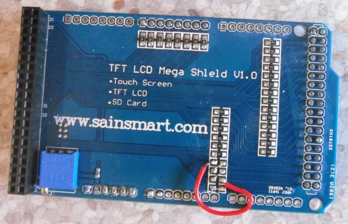
so trying to use the SD card slot doesn't work

Luckily after looking at the connections and doing a bit of searching, it seems 4 of the connections on the shield are wrong.

The solution is to remove the lower 4 resistors and wire them as per below which is the modified shield where the SD card slot works - take note Sainsmart and fix your shield

posted on: 02/06/2013 19:51:23

dave posted:

So I have to do this to mine ?
posted on: 03/06/2013 06:57:39

Dan posted:

So I have to do this to mine ?


Nope, yours is fine without it. I just wanted to show what needs to be done to be able to use an SD card with this screen.
posted on: 03/06/2013 12:35:16

Doc Holliday posted:

Hi Dan,
Package arrived today !
Now it´s my turn, . . .
order bit´s and pieces the next day´s

if a dummy like me get it - everyone could, . . .

to be continue, . . .

Ralf
posted on: 03/06/2013 21:32:57

dave posted:

Problem with the indicators I was planning to use they have normal bulbs in and not led one back to the drawing board well ebay
posted on: 04/06/2013 07:53:08

Dan posted:

Nothing to do now but wait dan is on its way get there Tuesday missed sat post by 5 mins


Hi Dave,

Received it today, I'll try to have a look at it tonight or tomorrow and get it back to you.
posted on: 04/06/2013 12:22:36

Dan posted:

Hi Dan,
Package arrived today !
Now it´s my turn, . . .
order bit´s and pieces the next day´s

if a dummy like me get it - everyone could, . . .

to be continue, . . .

Ralf


Hi Ralph,

Glad it got to you in one piece. The main thing that you will need to do is ensure that the Arduino Mega (that you need to get) you will need to add on a decent sized heatsink as explained earlier in the post as it gets hot[omg].
posted on: 04/06/2013 12:26:41

dave posted:

glad it got there in one piece what wiring do i need to get ?
posted on: 04/06/2013 13:37:18

dave posted:

seen something diff for the rear indicators on ebay
posted on: 04/06/2013 13:39:34

Doc Holliday posted:

Hi Dan,
here are the bits I orderd:

Arduino Nano V3.0 - ATmega328 Mini USB Board + FREE USB Cable

5x LM35DZ Precision Centigrade Temperature Sensor LM35

Arduino Compatible Mini magnetic reed modules

Bi/Uni AC/DC Current Sensor Module (arduino compatible) 150 A

I2C Tiny RTC DS1307 Real Time Clock Module AT24C32 Board for Arduino AVR MCU PIC

Male/Female PCB Connector/Header/Terminal/Housing/PC/Computer/solder (1 x 4 / 2 x 2 / 6 x 3)

Screened Alarm Cable Wire 4 Core 2m

SainSmart Mega2560+3.2" TFT LCD Shield+Touch Screen SD Reader 4 Arduino UNO


Did I also need this ? :

Important: You will also need to place a rectifier diode (1N5404) across the +/- connections of the motor to prevent back EMF damaging the relay.

Anything forgotten ? ? ?

waiting for delivery, . . .

thanks
Ralf
posted on: 05/06/2013 13:08:07

dave posted:

I just went down the the list mate you also need 2 project boxes
posted on: 05/06/2013 14:13:18

dave posted:

The bottom one on your list is for the front end got mine by making an offer for 33 quid uk seller free p + p :-)
posted on: 05/06/2013 14:18:40

Dan posted:

Hi Ralph,

Yep, you're list looks good, I can't think of anything else other than the necessary cabling/project boxes.

You will need a rectifier diode (1N5404) which you place across the motor +/- connections to protect the relay from nasty back EMP voltages

Dave: You need a diode on your's too, I'm sure you've already done it
posted on: 05/06/2013 18:59:51

dave posted:

Yep £1.54 from maplins lol all I need now is what wiring to get and a wiring diagram
posted on: 05/06/2013 19:20:22

Dan posted:

what wiring to get and a wiring diagram

Check out your c5 touch thread...
posted on: 05/06/2013 21:10:32

dave posted:

Wot conections plugs go on the header pins were do you put the current sensor and how do you connect the motor to the control box ?
posted on: 06/06/2013 12:14:54

Dan posted:

Wot conections plugs go on the header pins were do you put the current sensor and how do you connect the motor to the control box ?


Not sure what you're talking about RE: "connector plugs on the header pins" but here's a block diagram that may help you wire up the motor and current sensor:

posted on: 06/06/2013 17:04:11

dave posted:

Thanks for that dan the pins like the 4 at the side of the rtc and group of 3 x3 on the board top of the nano
posted on: 06/06/2013 17:19:45

Dan posted:

Thanks for that dan the pins like the 4 at the side of the rtc and group of 3 x3 on the board top of the nano


Ah right, they're not used. Don't worry about them!
posted on: 06/06/2013 17:22:58

dave posted:

Do you bolt the screen to the back of control box ?
posted on: 06/06/2013 18:00:34

Dan posted:

Do you bolt the screen to the back of control box ?


Huh? The control box goes at the back of the C5 (where the original would be) and the screen goes at the front (where the POD would be).

How you mount your screen on the front is up to you
posted on: 06/06/2013 18:26:00

dave posted:

sorry about that project box not control box or is there fitting kit ?
posted on: 06/06/2013 18:30:33

Dan posted:

sorry about that project box not control box or is there fitting kit ?


Ah right. Nope there's no fitting kit. I just cut a square on the front large enough for the screen to sit in, drilled a hole at the back for the cable, another hole on the left for the USB, but that's optional.

I drilled 2 holes in the back for bolts to go through to hold it to the POD case I used, but how you do yours is up to you.

My project box was 130mm x 70mm x 45mm and at that size I needed to shave about 2mm of the LCD PCB off to fit. At 130mm wide it fits perfectly between the 2 indents on the front of the POD.
posted on: 06/06/2013 18:43:35

dave posted:

cheers might put mine on a baseball cap lol joking
posted on: 06/06/2013 18:50:18

dave posted:

So I need 2 of them leads and a long 1 for the lm35 strapped to the motor ?
posted on: 06/06/2013 20:16:49

Dan posted:

So I need 2 of them leads and a long 1 for the lm35 strapped to the motor ?


Yeah, get your self a bunch of these, they're always useful for arduino projects.

I just got 3 bits of long wire (surrounded it with kitchen foil and heatshrink wrapped to prevent noise) or you could use some of that alarm cable if you have any left over?

Then add a connector for the motor LM35.
posted on: 06/06/2013 20:33:17

dave posted:

That's easy got the connector from doing the board and found a roll of alarm cable in the shed today after I got two meters from ebay
posted on: 06/06/2013 20:49:09

dave posted:

Hey doc when you get soldering on the out pins you have to cut the middle pin out and I've put a 4 pin male /female plug at the back of the screen box to make it easy ifyou have to strip down but that's up to u ? as for project box I think you could get away with 35 mm deep I had to put 4 x 3mm nuts and bolts 45 mm long on the four holes on the screen to hold it in place ? Happy soldering
posted on: 07/06/2013 20:42:20

Doc Holliday posted:

. . . I´m still waiting for the parts needed . . .

[center][/center]

[center][/center]nearly 66% arrived jet

... today the current sensor arrived ...

[center][/center]

. . . but no touchsreen or mega . . .

[center][/center]have to wait
[center][/center]

[center][/center]Doc
posted on: 18/06/2013 12:19:34

dave posted:

Its a pain waiting for the stuff to come
posted on: 18/06/2013 16:22:30

Doc Holliday posted:

Cheers Dan,
screen arrived now

. . . but as i follow your steps . . .

now i´m looking for few more parts like:


[img=http://www.c5owners.com/documents/images/sinclair-c5/touchscreen-2/large/sinclair-c5-L7809-heatsink-1.jpg]x[/img]

L7809 & heatsink & one for the mega - also for the nano?

do you find a way to make use of the usb instead of soldering extra wires on the mega?


Ralf
posted on: 23/06/2013 08:01:30

Dan posted:

Hi Ralf,

L7809 & heatsink & one for the mega - also for the nano?

Yeah after I sent you the board I realised the nano/mega may get hot so decided to add a 9V regulator as 9V going to the nano/mega generates much less heat.

If you're able to cut both 12V tracks on the PCB, one going to the Nano which is fairly easy:


And the one going to the connector (That goes to the mega) which is hidden under the 4 pin connector block, this would have to be removed to cut the track:


If you can't do this then adding a heatsink to the mega should get rid of a lot of the heat.


Back to your original question, yes, 1 L7809 and 1 heatsink for the mega (as above), the regulator will be fine without a heatsink if its only powering the nano, but do check when you have it all built to see if it gets hot, mine gets warm but not hot without a heatsink on it.

When I redo the board for 24V I'll get it fixed on the PCB so you don't have to cut anything

do you find a way to make use of the usb instead of soldering extra wires on the mega?

I didn't no, I have just soldered wires onto the back of the mega.
posted on: 23/06/2013 09:21:03

Doc Holliday posted:

Hi Dan,

24 V

I need a second C5, . . .

another question:

is it O.K. when I use 1N5401 instead of 1N5404 for the motor because of EMP/F?

(because I have some laying arround)

posted on: 24/06/2013 08:00:29

Doc Holliday posted:

find a listing of:

1N5401 Peak Repetitive Reverse Voltage
Working Peak Reverse Voltage
DC Blocking Voltage 100

RMS Reverse Voltage 70

1N5404 Peak Repetitive Reverse Voltage
Working Peak Reverse Voltage
DC Blocking Voltage 400

RMS Reverse Voltage 280

so the 5401 is to "small"?

the other Characteristics are the same, . . .
posted on: 24/06/2013 14:36:14

Dan posted:

find a listing of:

1N5401 Peak Repetitive Reverse Voltage
Working Peak Reverse Voltage
DC Blocking Voltage 100

RMS Reverse Voltage 70

1N5404 Peak Repetitive Reverse Voltage
Working Peak Reverse Voltage
DC Blocking Voltage 400

RMS Reverse Voltage 280

so the 5401 is to "small"?

the other Characteristics are the same, . . .


Yeah, you can use 1N5401, that is the same as can be found in the original control box.
posted on: 24/06/2013 18:19:25

Doc Holliday posted:

Hi Dan,
finally I get the last bits and pieces to go on with the project

but in the meantime I realized that there is a 24v version off it and crossthinking:

is there a possibillty - with some triggers or tricks - to make use both: 12 v & 24 v with the same equipment?

The board "looks" nearly the same - and I have to solder now anyway everywhere, . . .

maybe just a dream of mine, . . .

but before I make my try I did want to ask if there is a chance - so I have a C5 that we called here "eierlegende Wollmichsau" (get eggs, wool, milk & meat from one animal (C5))

or have to get another C5 for 24v?


Doc

posted on: 29/07/2013 19:30:58

Dan posted:

Hi Dan,
finally I get the last bits and pieces to go on with the project

but in the meantime I realized that there is a 24v version off it and crossthinking:

is there a possibillty - with some triggers or tricks - to make use both: 12 v & 24 v with the same equipment?

The board "looks" nearly the same - and I have to solder now anyway everywhere, . . .

maybe just a dream of mine, . . .

but before I make my try I did want to ask if there is a chance - so I have a C5 that we called here "eierlegende Wollmichsau" (get eggs, wool, milk & meat from one animal (C5))

or have to get another C5 for 24v?


Doc


Hi Doc,

At the moment you would need 2 C5's for 12v and 24v. I wonder what happens if you just give the uni-8 12v? Dave will probably know the answer.

Or would it be better to keep the 12v mode using a relay?

A project for another day I think. Now off to install some front indicators
posted on: 30/07/2013 16:53:55

Dan posted:

For those who haven't ventured into the world of LCD touchscreens on their C5 here's an interactive app of the screen:

posted on: 20/08/2013 18:35:57

dave posted:

This its d5 on the board is that to make the thing hover lol
posted on: 20/08/2013 20:05:31

Dan posted:

[quote=dave;939]This its d5 on the board is that to make the thing hover lol[/quote]

  I've got a pair of magnetic drive modules on order that will hopefully get the C5 to levitate freely.  I'll add a button to the touchscreen later to activate it
posted on: 20/08/2013 20:12:32

dave posted:

Lol order me. A pair
posted on: 20/08/2013 20:26:49

dave posted:

Dan what is the max watt can the aux lights handle ?
posted on: 27/09/2013 10:48:32

Dan posted:

[quote=dave;1198]Dan what is the max watt can the aux lights handle ?[/quote]

I'd keep it under 5 watt.  Should be enough to power a couple of led strips.  Depends also on what other stuff you've got connected. motor fan, main lights, indicators.  The mosfets can handle high current, its the pcb traces that can't
posted on: 27/09/2013 12:26:23

Jonatan posted:

Hey Guys,
I am sick of my old wiring. It had a thermal meldown, the last time I rode up our hill. Is there any way, someone could make the board for me? The Electrics are starting to get really anoying for me, as I can only do basic electrics or complicated Relay structures. Yet arduinos are way beyond my capabilities. What is the total price for the pieces? Of course, I can strip down my C5 and I wont worry while doing so, I dont care if my C5 will go down in its worthyness, I already opened up my Indicators and added LEDs. I want to use my C5, so that it is useful to me and I dont want to sell it anyways. Would it be in anyones capabilities to make one of these boards for me? Of course, I would pay that person. What would you want for this kind of work? Please, dont take this as a go yet, if your interested I would love to hear from you. Then we can discuss further.

Cheers,
Jonatan
posted on: 11/12/2013 23:18:24

Jonatan posted:

Hello,
sorry for bothering everyone again with this, but I would like to make one of these boards as I am REALLY annoyed with the crappy circuits inside my C5. Is there still a board or are there any instructions so I could add the components? Is it possible running the Xpod with a pedelec mode without the screen? Or, what Id aprieciate the most, could someone make one for me? Id pay that person the components and Id give that person for working on it for me. I can make all of the connections, but It would be so much better for me to get one. Also, it would make my C5 look more futuristic :)

Thanks a lot!
Jonatan
posted on: 27/05/2014 18:06:20

dave posted:

Time for bed
posted on: 27/05/2014 21:00:31

Jonatan posted:

Uh, very funny. Maybe you should go first :D
posted on: 27/05/2014 21:04:01

dave posted:

Been to bed been to work and now bk home all the info needed for the x-pod board is in the project sections it will cost approx 150 Gbp to make and time to sit there soldering hours on end then there the waiting weeks for parts from china aswell you will need the screen to use with rear end setup
posted on: 28/05/2014 13:36:48

dave posted:

Also got a spare 12 v board made with current sensor ready to rock and roll
posted on: 28/05/2014 13:38:18

Dan posted:

Hi Jonathan,

Sorry but I do not have any more of the xpod boards left, the whole thing is extremely complicated and time consuming to build. If you're having problems with the POD/CB setup you'd be better off running your C5 directly from a relay and maybe add a battery monitor to show you voltage/current/temp.

Thanks!

Dan
posted on: 28/05/2014 18:04:02

Jonatan posted:

Hellur everyone!

@Dave
A spare one for sale, or for personal use? :)

@Dan
Yeah, I would but I really need the pedelec mode :/ Thats my problem, as in germany the 3 wheeled vehicle rule doesnt apply in germany, It actually applies as a motorcycle :/ My parents dont allow that...

Thanks for your replies!!!
Johnny
posted on: 28/05/2014 20:48:07

dave posted:

Yip for sale will need screen and wiring to make it work will post a pic Tomorow after work will need software on the screen tho software on nano there
posted on: 28/05/2014 21:12:21

dave posted:

The ped mode you need another reed on rd 2 on the board
posted on: 28/05/2014 21:14:12

dave posted:

This what you after Jon

posted on: 30/05/2014 15:58:59

Jonatan posted:

Yes, awesome!!! Please read my PM, so we can talk about how much you want!

Jonatan
posted on: 30/05/2014 16:04:05

Jonatan posted:

Hello,

Now, to the great news:
I bought Daves back module (almost :D ) and the Sainsmart touch screen (I won an auction 3 mins ago :D )! Hopefully il finally be a happy owner of a C5 soon! Now, to the components: What do I need for the front? Theres a lot of goofy things going around on the touchscreen board I need to figure out. Is there anyone I could contact who would be willing to help me when I am in need? Thanks a lot!

Jonatan
posted on: 30/05/2014 18:09:38

Jonatan posted:

Hi everyone,
got it all sorted. I just have one important question: Who knows how the connectors on Daves board are called? They seem different to the ones Dan used and I would love to have all components arriving this week, even next. Please help me sort things out!

Yours, Jonatan
posted on: 02/06/2014 09:29:05

dave posted:

The cream ones ? Pcb connectors just need wires putting in them
posted on: 02/06/2014 21:55:30

Dan posted:

The connectors are these:

http://www.ebay.co.uk/itm/400344210802?var=670048585836

All the links to the components can be found here, have a good read:

http://www.c5owners.com/sinclair-c5-projects/c5duino-arduino-based-control-box


posted on: 03/06/2014 06:22:14

Dirk-Jan posted:

is this allready out of beta testing? If so, where can i buy one?
posted on: 11/09/2014 08:33:31

Dan posted:

Hi, Sorry its no longer available. If anyone has a problem with a POD on their C5 its best to remove it all together and run it directly from a relay and perhaps add a car battery monitor as a display.
posted on: 12/09/2014 11:03:39

dave posted:

You can have mine with the c5 and disc brakes mods and alloy gearbox mod for 1000 pounds pick up only from hull
posted on: 13/09/2014 15:59:52

dave posted:

And it's got UNi 8 24 volt controller too
posted on: 13/09/2014 16:03:45

Dirk-Jan posted:

Hi,

Sorry its no longer available. If anyone has a problem with a POD on their C5 its best to remove it all together and run it directly from a relay and perhaps add a car battery monitor as a display.


In the netherlands you gotta have an pedalec mode to be legal. Any schematics available so i can print my own pcb and solder it?
posted on: 15/09/2014 09:12:23

wildfireone posted:

Hello Dan,

I know this is an old subject but I am looking into this as a possible replacement for my control box and pod. Is the circuit schematic available for a replacement control box (I know Dirk has already asked). Would like to have a go at making one myself

Thanks

Fran
posted on: 05/08/2015 17:05:40

Dan posted:

Sorry yeah there are no more PCBs available for this. You're probably better off just using a relay straight to the battery with a car temp/voltage meter in place of the POD
posted on: 05/08/2015 17:23:44

wildfireone posted:

LOL, This is kind of how it was when I got it (volt meter anyway). I am hoping someone might have one that someone can sell me a Pod, however I was hoping you might of been willing to share your PCB circuit schematic for the c5duino. Would try and make one of my own, probably with strip board!
posted on: 05/08/2015 17:38:24