
Sinclair C5 with Touchscreen LCD Display
This has now moved into the X-Pod section.
For a long while I've been playing around with an Arduino board and various sensors/relays and wondered if I could use them to construct a new control box/display for my plain old 12V C5 as a substitute for the original control box/pod which my C5 didn't have when purchased a few years ago.
The choice of using an Arduino board was simple: They are cheap, there are lots of sensors/modules available and you can program it in a language very similar to C++ on your PC.
3.2" TFT LCD Touchscreen Display
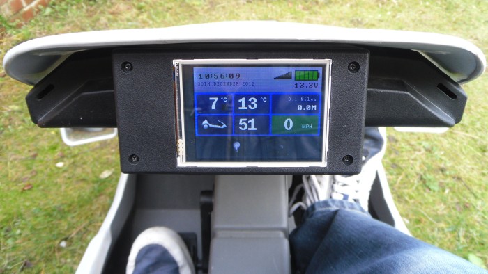
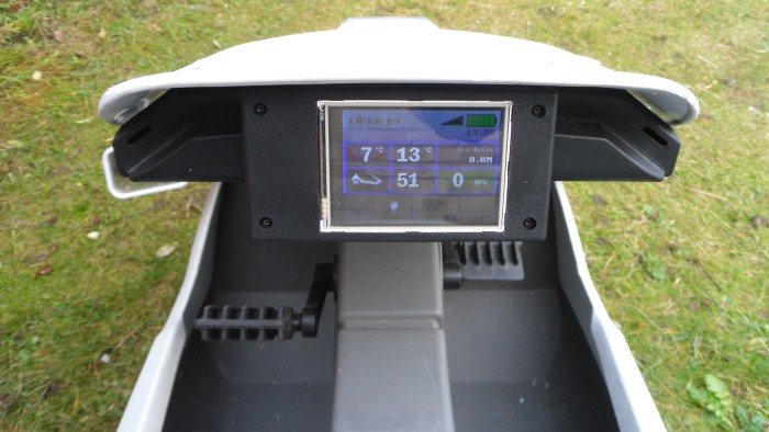
The first thing I wanted to do was create a display with a decent pixel resolution, this would relay all the important sensor information to the C5 driver. The display I found was a nice 320x240 pixel display that supports 16-bit colour and has a built-in touch screen. Perfect!
So started the C5 Touchscreen. Deciding what sensors I would need were fairly simple: I wanted to measure battery level, speed and motor temperature. I wanted to control the C5 motor with an analog input (Throttle switch). I wanted to show some visual indication when the indicators were on and have a hazard light button all managed in software.
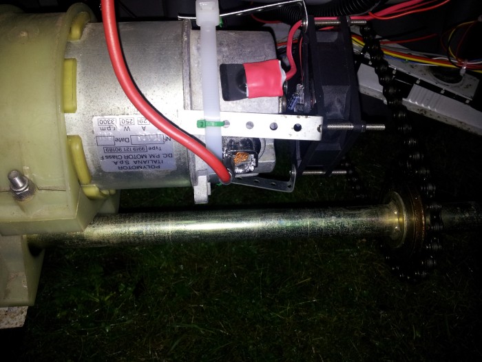
The Arduino board itself has the ability to manage many Digital/Analog I/O ports. Some pins support PWM which is great for creating a variable speed cooling fan to keep that all important C5 motor chilled. The logic for it is fairly simple: At 15°C or lower the fan is off, at 25°C or higher the fan is on at full speed and for all temperatures in between the fan speed will vary.
Due to the touchscreen I'm using we have to use the Arduino MEGA board which is larger than the plain UNO board but comes with many more I/O ports.
As this is a touchscreen I want to add various options to configure the Time/Date, MPH/KPH, security PIN and any other settings I decide to add.
Feature List
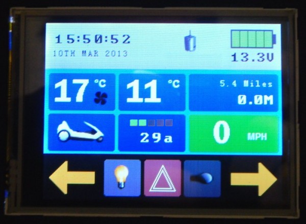
Here is a list of what the new C5 control unit/display does:
- Display battery voltage.
- Display ambient temperature.
- Display motor temperature.
- Display motor Amp consumption, 5 color meter to show load.
- Display speed (MPH/KPH).
- Variable speed cooling fan (Software controlled based on motor temperature).
- Motor control 12V relay (Software controlled based on handlebar switch input/disabled when motor temperature is > 70°C).
- Visual indication when the left/right indicators are on.
- Indicator flasher in software.
- Hazard toggle button, software controlled.
- Front/Rear light toggle button, software controlled.
- Underneath Blue LED strips with toggle button, software controlled.
- Display time/date.
- Display total/session mileage.
- Security PIN lock screen, all electronics are disabled until the correct PIN is entered.
- Motor over heating warnings, motor disabled when the motor temperature exceeds 70°C.
- Battery voltage warnings, motor disabled when battery voltage drops below 10.0V.
- Motor load warnings, motor disabled when load exceeds 120amps for a period of time.
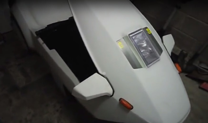
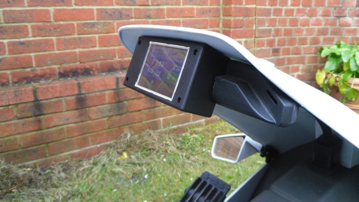
As you can see from the pictures I've mounted the display into a small project box and taken the casing for a broken POD and, after a bit of sawing, I've fitted the new screen and it's box inside the original POD casing making it look cool and kind of original.
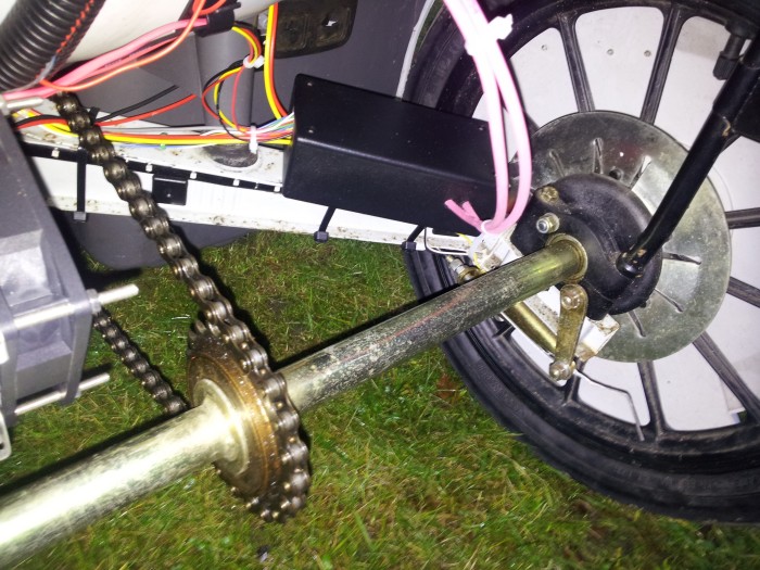
At the back of the C5 I have added a new Black plastic box containing a new circuit board that allows the lights to to switched on/off, the motor relay and other bits for handling the cooling fan/handle bar switch and indicator switched. This is mounted where the original C5 control box would have been found.
The Software
All of the above isn't much use without the software to drive it and this is where a knowledge of mid/low level programming comes in. Arduino itself is programmed in something similar to C++. It's fairly easy to knock out a program to flip an LED on and off in a loop, indeed, the first demo I did was exactly that.
Luckily my background is in web development and before that games programming in old Z80/ARM assembler so the prospect of writing some C++ wasn't a problem.
As this is a touchscreen application I created several classes to represent colours, buttons, screens etc that grouped together both render and input (touch) functions. The LCD screen comes with a fairly basic set of rendering commands such as: Drawing squares, lines and fixed width font rendering using bitmaps.
The software to drive the display and control the various sensors is mostly done though it may need tweaking after some more testing is performed. The security PIN screen is ready and working. The PIN can be set at any time and needs to be entered when you first power on the unit.
I am using an RTC (Real Time Clock) module that as well as providing a means of maintaining the current time it also provides 50 bytes of NV RAM (Non Volatile Memory) that allows me to store things like the PIN code and other values such as total mileage that will persist even when powered off.
Want One?
Although this is a one-off project, if anyone out there would like to try something similar and would like to use/get hints from the code then head on over to the Building the LCD Touchscreen page for more information.
Component List (Work in Progress)
Here is a list of the components needed to build the display section and back-end circuit board. These are all readily available on the internet. Note: Links are from suitable items on ebay, I'm not benefitting from putting these links here, it's just to make it easier for you to find the right component!
Reference Circuits
I'm no expert at electronics, this is my first serious project and my first with an Arduino board. There is no circuit diagram, this project has been knocked together using several resouces I found whilst researching Arduino sensors. All the circuits used here are from various sources around the internet. The following will help when building the circuits for the back-end section:
- MOSFET Motor/Light/fan control: http://bildr.org/2012/03/rfp30n06le-arduino/
- Button press detection: http://www.arduino.cc/en/Tutorial/Pushbutton
- Temperature sensor: http://www.youtube.com/watch?v=_fNto4JOu4E
Display Section Conponents
My C5 Touch has none of the original electonics or wiring. There is a switch attached to a 12V relay that enables the front screen and motor power. The display at the front is composed of the following:
- Arduino MEGA
- Sainsmart 3.2" Touchscreen LCD Screen
- Sainsmart LCD Shield
- RTC Module
- LM35 Temperature Sensor
- PCB Stripboard 25 x 64mm
- 10K Resistor
- 330Ω Resistor
- 10-Way PCB Pin Header x 2
- Arduino Stackable Header / Connector 6 and 8 Pin (If mounting the PCB under the main Arduino board).
- Project Box 130x68x44mm (You may need a larger one depending on how you connect everything to your Arduino board).
- PCB angled header pins x 40
The Arduino mega/shield/LCD screen can be purchased together or as separate items. Sainsmart are the only makers of this size LCD screen for the Arduino as far as I know: Sainsmart Arduino Touchscreen LCD Screen. You can use other LCDs though the software would need a significant rewrite to work with anything other than the Sainsmart screens.
Back-end Section Conponents
- 12V Relay suitable for controlling the C5 Motor
- MOSFET IRFZ44N x 5 (For turning the indicators, front/back lights on/off, cooling fan and Blue LED strips)
- 10K Resistor x 10
- 12V 70A relay
- Reed Switch & Magnet
- 100A Bi/Uni DC Current Sensor Module (from Ebay)
- LM35 Temperature Sensor
- PC cooling fan
- PCB Stripboard
- 10-Way PCB Pin Header x 2
- 60A screw terminals x 4
- 60A Red/Black cable 1.5M
- Cable to connect the front display to the back control box (20 core) about 1.5M long (Same length as the original cable used to connect the POD to the control box)
- PCB screw terminals x 6
- PCB header pins x 40
- Project box 150x100x60mm
Videos
Here is a video that briefly shows the features of the touchscreen in action.