Please note: The forum is now closed to new submissions. All the existing forum topics and posts are still available, however new topics cannot be created. If you need Sinclair C5 advice please use the C5 Owners Facebook Group.

Dan posted:

Having figured out how to integrate a touchscreen LCD display into a Sinclair C5 using the rather fabulous Arduino Mega 2560 board I thought I would take it a step further.

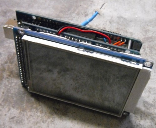
One of my main concerns with the original C5 Touch is its use of a prototype PCB which, although it allowed me to put the whole thing together quickly and cheaply there will be issues with the home soldering not standing up to the test of time in a C5 that rattles around.

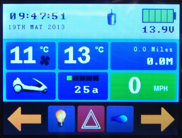
The original display used a 320x240 colour touchscreen display:


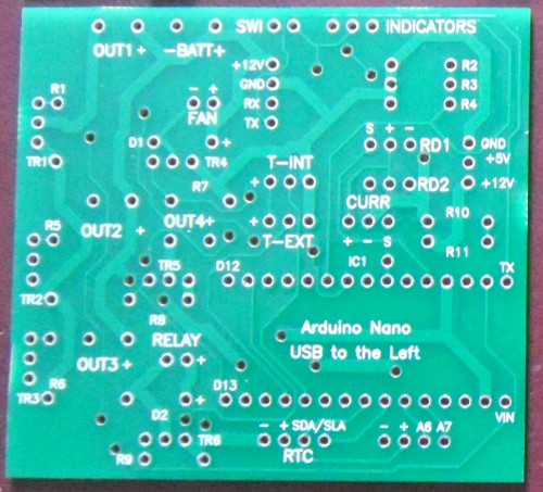
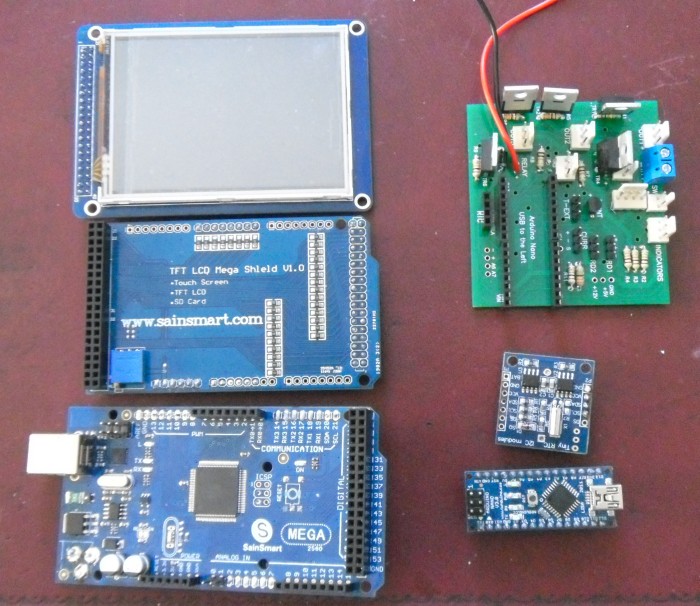
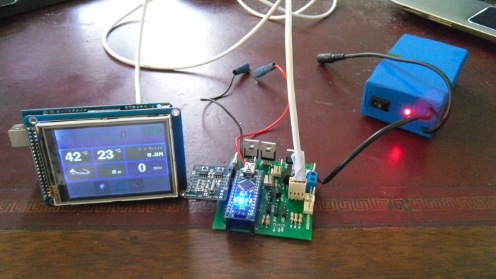
With the new re-designed unit I plan split it into two separate parts. The display section, which will reside where the original POD is and an all new control box which will sit where the original, ahem, control box is. I've done a rough design of the new control box PCB:


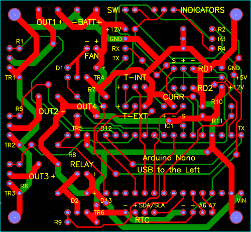
Like the original C5 Touch it will support indicators, front/back lights, hazards, underside lighting. The motor (via a 12V relay) will be controlled by the board, internal/motor temperature, motor current, battery voltage will be monitored.

There will be two reed switches, one to measure the speed of the C5, the other, will be mounted on the frame at the front to measure peddling speed.

I'll post more photos as I make progress.
posted on: 03/05/2013 19:29:22

dave posted:

When will it be ready for testing ?
posted on: 03/05/2013 20:16:43

Dan posted:

When will it be ready for testing ?


Give me about 2-3 months

It's in the design phase, so nothing physical exists yet. Basically what I'm doing is designing a circuit board, based on the original prototype board I made, that can be professionally printed.

When I've got the board sorted then the front-end screen should be fairly simple to put together. The software will need an overhaul as I don't intend to have a 20 core cable connecting front-end to back-end like the prototype, rather I want to use a serial connection which uses far less wires.
posted on: 05/05/2013 05:19:58

dave posted:

The way you work it will be ready by the end of the month
posted on: 05/05/2013 09:36:32

Dan posted:

The way you work it will be ready by the end of the month


I wish it was that quick, it's getting the board professionally printed that can take a while (usually about a month).
posted on: 06/05/2013 09:54:11

dave posted:

Can I have the prototype
posted on: 06/05/2013 15:07:17

Dan posted:

Can I have the prototype


You can sure have one of the prototype boards when they turn up and I've done everything else to make it work. The original is staying on the C5, it really is too much of a hassle for me to remove it all

posted on: 06/05/2013 19:09:27

dave posted:

Cheers dan can'Wait
posted on: 06/05/2013 20:02:28

Dan posted:

I have been splitting the software into 2 separate Arduino projects. The new C5 Touch will make use of 2 Arduinos. A Nano in the back-end "control box" and an Arduino Mega + LCD at the front which sits where the POD used to be.

The new control box will control all the sensors, lights, indicators, motor and cooling fan by itself. At the centre of it is an Arduino Nano which is plenty powerful enough to manage all those tasks.

The front end display section will simply be the Arduino Mega, Shield and LCD, which are all off the shelf components. The only customisation is the 4 pin connector on the back which exposes the 2 serial pins (TX & RX) plus GND and VIN.

Connecting the display and control box is a shielded cable consisting of 4 cores.

The 2 Arduinos communicate to each other using a serial method, thus greatly reducing the number of wires going from the front of the C5 to the back. My original C5 Touch prototype used a single Arduino Mega that handled all the sensors etc and used a 20 core cable to connect front to back!

This separation of display and functionality will in future allow the use of different displays. To create a custom display all one would need to do is choose a screen/hardware platform (Arduino, Raspberry Pi, ARM etc) and write the necessary software to communicate with the new control box over the serial connection.
posted on: 11/05/2013 06:07:57

dave posted:

told you would have it done before end of the month lol that's 2 nanos on. Order
posted on: 11/05/2013 16:16:28

Dan posted:

Hi Dave,

that's 2 nanos on. Order

This project only needs one Nano and one Mega/shield/LCD:

http://www.ebay.co.uk/itm/SainSmart-Mega2560-3-2-TFT-LCD-Shield-Touch-Screen-SD-Reader-4-Arduino-UNO-UK-/280931953825

There's a couple of extra modules needed, an RTC module:

http://www.ebay.co.uk/itm/121079759380

Current sensing module which is optional, if you want to show motor current:

http://www.ebay.co.uk/itm/50A-100A-150A-200A-Bi-Uni-AC-DC-Current-Sensor-Module-arduino-compatible-/111040360152

If you want the unit to measure speed you'll also need a Reed switch. I need to find the link where I got mine from, I can't seem to find this on ebay now.

Do a couple of searches on ebay to find the cheapest, the above links were the first I could find

I hope you enjoy soldering/wiring, there will be a lot of it on this project

told you would have it done before end of the month

Well, whilst waiting for the boards I can at least sort out the software and the C5 wiring.
posted on: 11/05/2013 16:46:10

Dan posted:

Also, the front/back lights must be low power LED lights.

If you're planning to implement indicators, they must also use LED bulbs, the original bulbs use too much power and will probably damage the board.
posted on: 11/05/2013 16:53:55

dave posted:

One nanos. For the ula mod thanks for the links dan I'll av alook cheers

Can't find a reed switch and magnet that you used on ebay ?

Still can't find tbe red reed switch ? And could this be made to work on 24 /36 volts ?
posted on: 11/05/2013 17:28:10

dave posted:

You will dan once you go 24 you will never go bk to 12 lol if I get this up and running I'll treat my self to a motor with metal cog of chas and metal gear cog from marra and go to work on it 8 miles each way
posted on: 19/05/2013 17:53:33

Dan posted:

The boards have finally turned up:


What you will need:


Started soldering on some components:


The completed board:


All wired up, none of the sensors return meaningful data until its on the C5:


This will now be moving over to the BETA program section of the forum.
posted on: 20/05/2013 17:09:58