


Constructing the X-POD
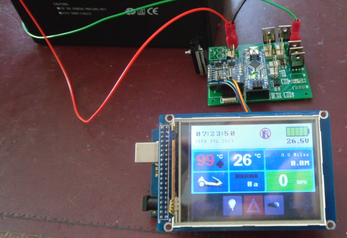
The X-POD is split into 2 components. The control box (C5duino) and the display (Touchscreen LCD). The control box is mounted at the read of the C5, in the same position as the original C5 control box. The display box is attached to the front where the C5 POD is located.
Control Box
First we shall start with the control box as this is the most complicated. I have designed and printed a custom PCB which forms the basis of the control box. You will need to purchase the components listed below and slder them to the board.
Control Box Component List
To help sourcing the components needed to build the control box I have provided links to the relevant items on Ebay. It is up to you where you get your components from, the links I provide are purely to show you the item I am talking about.
These components need to be soldered to the control box PCB:
- 10kΩ Resistor (x9)
- 3.9KΩ Resistor (x1)
- 100KΩ Resistor (x1)
- Diode 1N4001 (x3)
- LM35 Temperature Sensor (x1)
- IRF530 N Channel Power MOSFET (x6)
- 7809 Regulator + Suitable Heatsink (x1)
- Single Row PCB Header Sockets 15x2, 4x1 & 5x1
- 2 way Male/Female PCB Connector (x7)
- 3 way Male/Female PCB Connector (x2)
- 4 way Male/Female PCB Connector (x1)
- PCB Header Pins (x6)
- PCB Male Spade Terminal (x3)
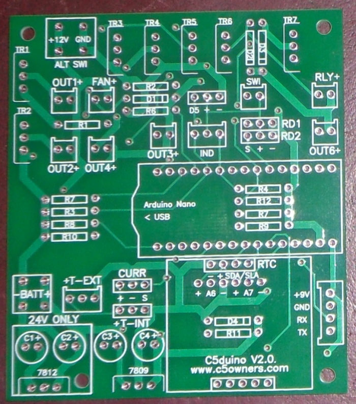
When you have all the components this is where they need to go on the PCB:
- IC1 = Arduino Nano
- R1-R9 = 10kΩ Resistor
- R10 = 3.9KΩ Resistor
- R11 = 100kΩ Resistor
- D1-D3 = Diode 1N4001
- TR1-TR5 = IRF530 N Channel Power MOSFET
- RD1 = Reed Switch
- CURR = Current Sensing Module
- T-INT = LM35 for Ambient Temperature
Additional components for the control box. These are not soldered to the PCB but rather will be connected to the PCB:
- Arduino Nano (x1)
- Reed Switch (x1)
- 150A Current Sensing Module (x1)
- RTC Module (x1)
- Large Project Box 145mm x 100mm x 60mm (x1)
- 12V 70Amp Relay (x1)
- LM35 Temperature Sensor (x1)
When you have the above components they need to be connected to the PCB:
- IC1 = Arduino Nano
- RTC = RTC Module
- RD1 = Reed Switch
- CURR = Current Sensing Module
- T-EXT = LM35 for Motor Temperature
- RLY = Motor Relay
Electrical Cable
To connect everything together you will need the following cable:
- 4 Core shielded cable (2m)
- 70amp rated cabled for the motor conenctions
- Suitably rated cable to connect lights/indicators to the control box
LCD Display
Construction is much simpler than the control box, the only modification needed is to create a connection between the VIN, GND, TX1, RX1 on the Arduino MEGA to allow a connection to be made to the control box at the back of the Sinclair C5.
To help sourcing the components needed to build the LCD Touchscreen I have provided links to the relevant items on Ebay. As usual, it is up to you where you get your components from, the links I provide are purely to show you the item I am talking about.
- Sainsmart 320x240px Touchscreen LCD Screen/Shield/Arduino MEGA (x1)
- 4 way Male/Female PCB Connector (x1)
- Suitably sized Project Box 130mm x 70mm x 45mm (x1)
The Arduino Mega
The pins highlighted below need to be attached to the 4 way connector. I did this by running 4 wires from each pin to a small PCB stripboard which had the connector soldered on.
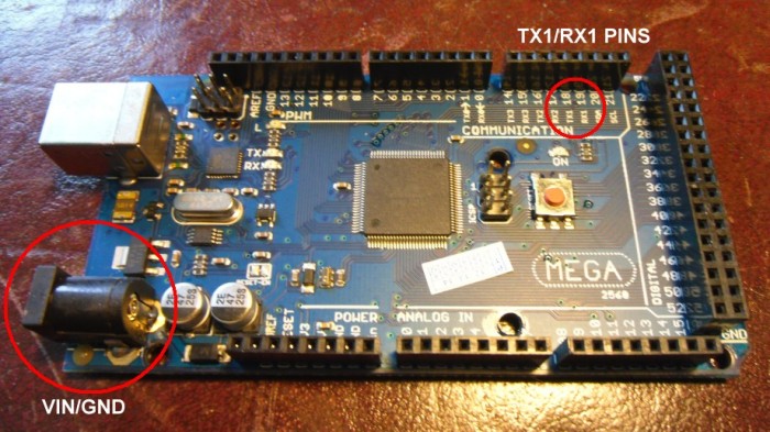
The wiring of the connector must match the connector on the control box circuit board, except TX1 & RX1 must be reversed. So TX1 on the Arduino Mega must be connected to RX on the control box board and RX1 (On Arduino Mega) must be connected to TX on the control box.
Gallery
Some images showing the construction of the board that will help with positioning of the components:
