


Prescott Testing & C5 Motor Protection By Perran Newman
Prompted by the recent sale on Ebay of photos taken at Prescott, I've wracked my brain to recall the day I spent with the development team from Lotus at this famous hill climb venue. Prescott is owned by the Bugatti Owners Club and this was my first visit even though I have attended several VSCC events at other venues.
The objective of the day from my perspective was to access the motor overheat protection systems for which I had been responsible as part of the overall electrical system. Lotus were there to explore downhill braking, fade and overheat characteristics.
I had 'instrumented' a C5 with a data logger so that the temperature of the motor case and the temperature inside the drilled out armature shaft could be recorded. It is worth digressing here to describe the thinking behind motor protection on the C5 as this, together with the ‘fuel gauge' were my main areas of concern. The rest of the system electrics was straightforward engineering but these two areas required creative and well tested circuit design.
When an electric motor is connected to a battery, the motor can easily be loaded to a point where it will eventually fail due to overheating. The nominal 250 watt rating of the C5 motor is a measure of its shaft output peak power which is achieved at approximately half its no-load speed. At speeds less than this, the current will increase further, output shaft power will drop and motor heat dissipation will rise. The ability of the motor to get rid of this heat depends on the local ambient temperature and the speed of rotation where heat is lost to passing air. A limit is reached when the armature windings get so hot that their insulation breaks down.
There is no simple way to measure armature temperature as this is the rotating part of the motor. The solution adopted was to drill a hole into the end of the shaft and bury a thermistor (a temperature sensitive resistor) below the armature position. Because the hole diameter was so small, the peripheral rubbing speed was also low and the thermistor was able to survive without abrasion.
Before this solution we looked at having a ‘thermal model' of the motor mounted against the case. The model would have comprised a small heating element carrying a fraction of the real motor current, a slug of metal representing the mass of the armature and an insulating block representing the thermal resistance between the armature and air. Placing the model in contact with the motor case would have been the 'real world' feedback element to allow the heater temperature to be a reasonable indication of the true armature winding temperature. This work was subcontracted to an engineering colleague at my previous place of employment. In the end, lack of sufficient data to calibrate the model and the much simpler - hole in the shaft idea, won the day. It was a fraught time as I was convinced that without a working solution we would substantial motor failures.
In the C5 there are three levels of motor protection as follows:
- Deliberate stall or near stall conditions. The motor current is integrated against time and if it exceeds a preset level, the motor relay is locked off. It requires the power to be removed (I think total power removal) and then replaced to reset this condition. A stall is detected within 3-4 seconds.
- The armature shaft temperature sensor has two threshold levels. At the first level, warnings are sounded to tell the user that protection is imminent. At the 2nd level, the motor relay is disabled until the temperature falls again.
- Motor case temperature is monitored using a bi-metallic switch. If it opens, the motor relay is disabled until the sensor resets.
History seems to have proved that these 3 protection systems prevented motor failures which in the period before SVL went into administration were virtually unknown.
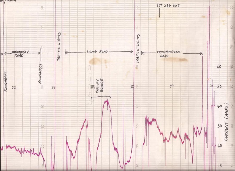
Returning to Prescott, I assume that I recorded data that confirmed the protection systems were adequate. Unfortunately, after 30 years I don't remember such details although my project files which I have kept might give more information. Remember that this is before simple cheap data loggers were available. For other experimental recordings I made my own form of motor current data logger which I still have. The motor current signal in the control box was used to vary the frequency of a oscillator. This signal (in the audible range) was recorded onto a miniature tape based dictating machine. Back in the lab, the reverse process took place and the resultant signal - a varying voltage was played back using a pen recorder. Amazingly, I still have some of these plots and for those of you who know Cambridge, the annotation of street names is amusing. This plot must have been made after the launch as it was a real C5 which could not of course have been seen on the streets any earlier. I think I was looking at the response of the ‘fuel gauge' under real world conditions.
Back at Prescott, I do vividly recall one event that led to major revisions to the braking system. One of the C5's was descending the hill, braking all the way when there was a loud bang. The front wheel plastic had softened sufficiently to allow the inner tube to escape the rim and burst.
A steel rim would have been the solution but this was not adopted probably for financial reasons. A heat dissipating plate was subsequently added to the rear brake drum and the front/rear balance was changed to throw more load onto the rear. It was unfortunate that the major advances in bicycle brake technology came a little too late for the C5. Owners will be well aware of the brake limitations, the worst of which is grabbing of the rear brake due to wear and distortion.
It would be great to see scenes from the day I spent at Prescott again. If anyone reading this piece knows who might have purchased the slides on Ebay, I would be delighted to hear from them via the contact address for this site [email protected].
