


Sinclair C5 New POD ULA Replacement Module
Here I present a project I have spent some time working on. A project that I hope will help Sinclair C5 owners who have run into the age old problem of having a faulty ULA chip in their POD.
The solution I present here is not a straight swap whereby the POD will continue to behave as a normal POD would with an original, working ULA. Rather this solution provides the following functionality:
- Battery Gauge (Right LED's)
- Temperature Gauge (Left LED's)
- Warnings for when the battery is low or the temperature is too high with motor lock out if either conditions occur.
- Straight swap with the ULA chip. No modifications necessary to the POD or control box.
Note: The one important function of the original ULA, the motor current display, is not included in this replacement ULA project. The left LED bar is now a temperature gauge. Perhaps in a later version I will look to see how we can have a motor current display.

Necessary Components
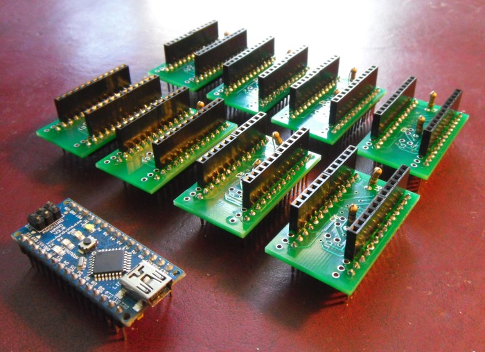
I have tried to minimise the number of custom components needed for this project. Only the circuit board is custom made.
- Custom PCB
- Arduino Nano V3
- Stackable Long Header Pins (6 pins) x4
- Header Pins (14 pins) x2
- R1 15kΩ Resistor
- R2 4.7kΩ Resistor
One of the main goals of this project is to create a module that is a simple plug-and-play solution that doesn't require any modifications to either the POD or the control box. The benefit being that if you should later find a working ULA chip it is very simple to put back in.
Constructing the Adapter
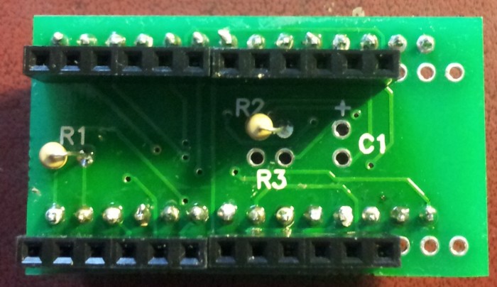
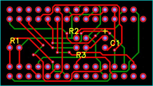
The top of the circuit board is identified with the markings R1, R2 etc. R1 should be on your left.
Start by soldering the 2 resistors to the circuit board. R1 is a 15kΩ Resistor and R2 is a 4.7kΩ Resistor. When they are in place solder a row of 14 Header pins to the top of the PCB (in the 14 holes on the board) so the long side is pointing down.
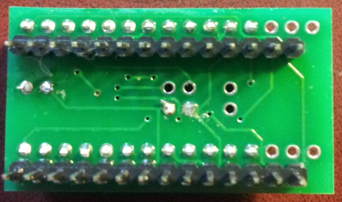
Then solder two of the Stackable Header Pin blocks (total 12 pin) to the next row of holes down. Note there will be 3 empty holes, this is fine, they do not need to be connected. Once soldered, using some wire cutters, cut off the excess length from the pins.
Solder the remaining 14 Header pins to the bottom section of the board, in the row of holes 2nd from the bottom. Solder the other 2 Stackable Header pins to the very bottom of the board, again there will be 3 empty holes to the right that will not be used. This completes the soldering part of the construction.
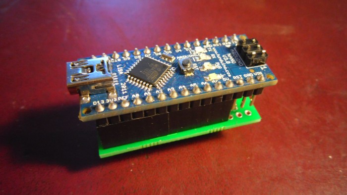
Inserting the Arduino Nano
The Arduino Nano can be inserted into the top of the board (USB socket to the left), the 3 pins on the right of the Nano will hang over the edge of the Stackable Header pins. These pins do not need to be connected to the circuit board.
Uploading the Software
The Arduino Nano needs the POD-ULA software uploading to it before anything will work. This can be done by installing the Arduino IDE (Available for free from www.arduino.cc), downloading the source code from the link below and clicking the compile/upload button in the IDE.
Installation
Note: Before you begin you need to be careful when handling the ULA chip and the Arduino to ensure you do not allow static electricity to destroy these components. An anti-static wrist strap is advisable when handling these delicate electronic components.
Remove the POD from the C5, disconnecting the Red connector cable. Remove the 2 screws from the back and remove the front cover:
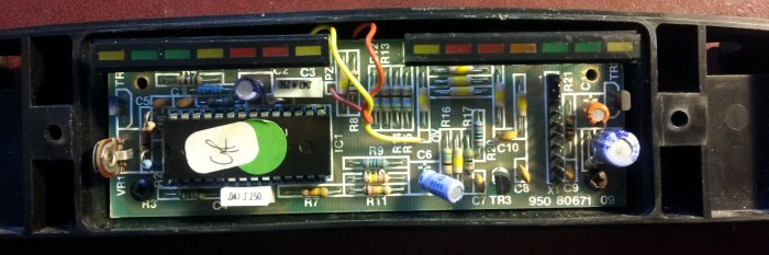
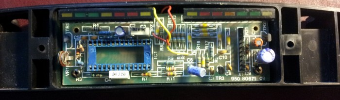
Gently remove the ULA chip on the left, either using an IC extractor tool or with a small, flat headed screwdriver:
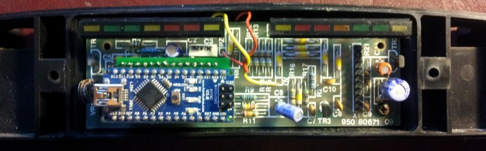
Insert the POD ULA replacement board, being sure to line up the pins on the underside of the board with the ULA socket:
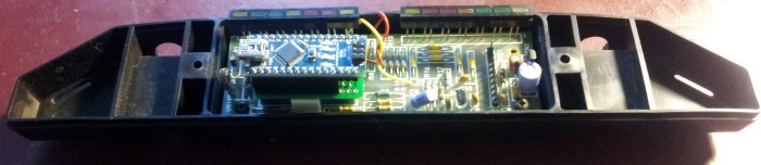
Put the POD cover back on and screw it back together. Then re-attach it to the C5 and you will be ready to go.
Testing the POD ULA Replacement
With the rear drive wheel off the ground, power on the C5. The battery gauge on the right should illuminate and the temperature gauge on the left should light up with 2 green LED's, or less depending on how warm it is. Click the handlebar switch to ensure the motor works correctly, with those tests complete it is ready to be used.
Operation Instructions
The left section of the display is for motor temperature. When in a cool state there will be 2 Green LED's lit. As the temperature increases, the LED's change from Green, to Yellow and then to Red. When 2 Red LED's are displayed, the temperature of the motor has exceeded 60°C. When the temperature reaches 70°C you will hear a tone coming from the POD and the motor cannot be used. Any attempt to use the motor whilst in an overheated condition will result in a tone from the POD.
The right part of the POD display is for the remaining battery voltage. With a fully charged battery this will be fully illuminated and will decrease as the battery voltage decreases. When the battery is low a tone will be generated by the POD and any attempt to use the motor whilst in a low battery power condition will result in a tone from the POD.
